Build your own GlowTracker
 | 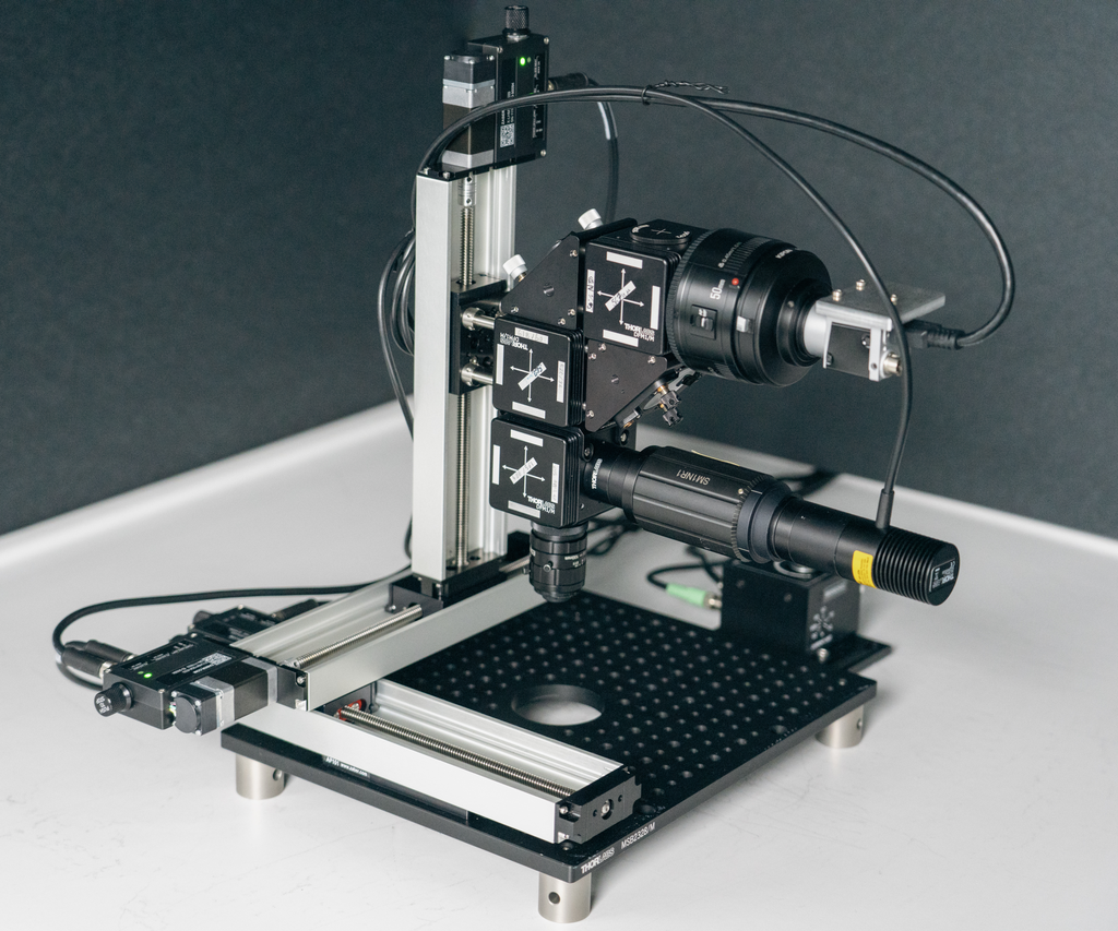 |
Steps for assembling your microscope
Assuming you have all the parts from the parts list available, you should be able to assemble the microscope in about two hours and have a fully functional tool.
Tools
You should have a metric Thorlabs Balldriver & Hex Key Kits, and an SM1 spanner wrench handy. A tiny flat-head screwdriver is useful for adjusting the camera orientation.
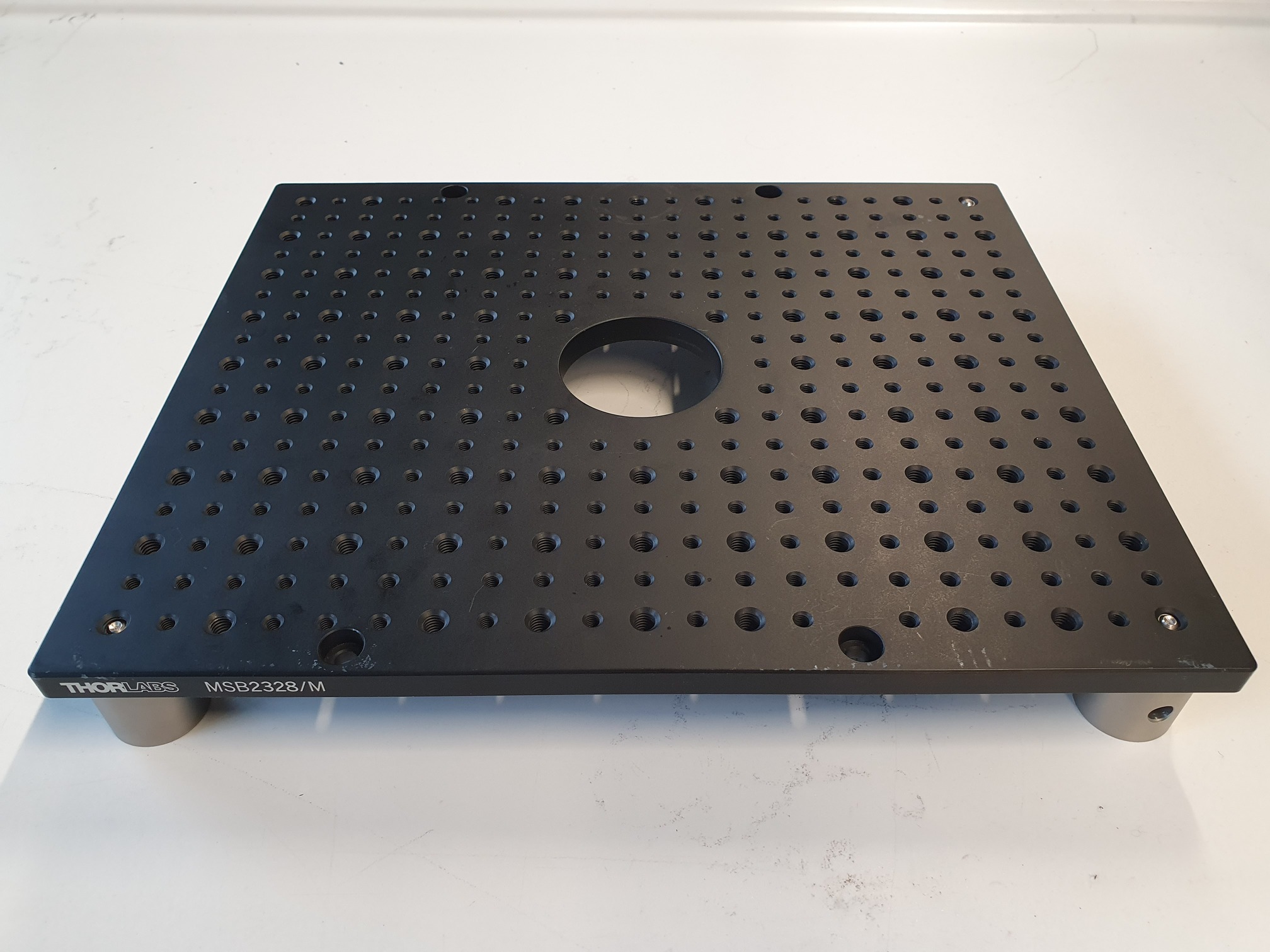
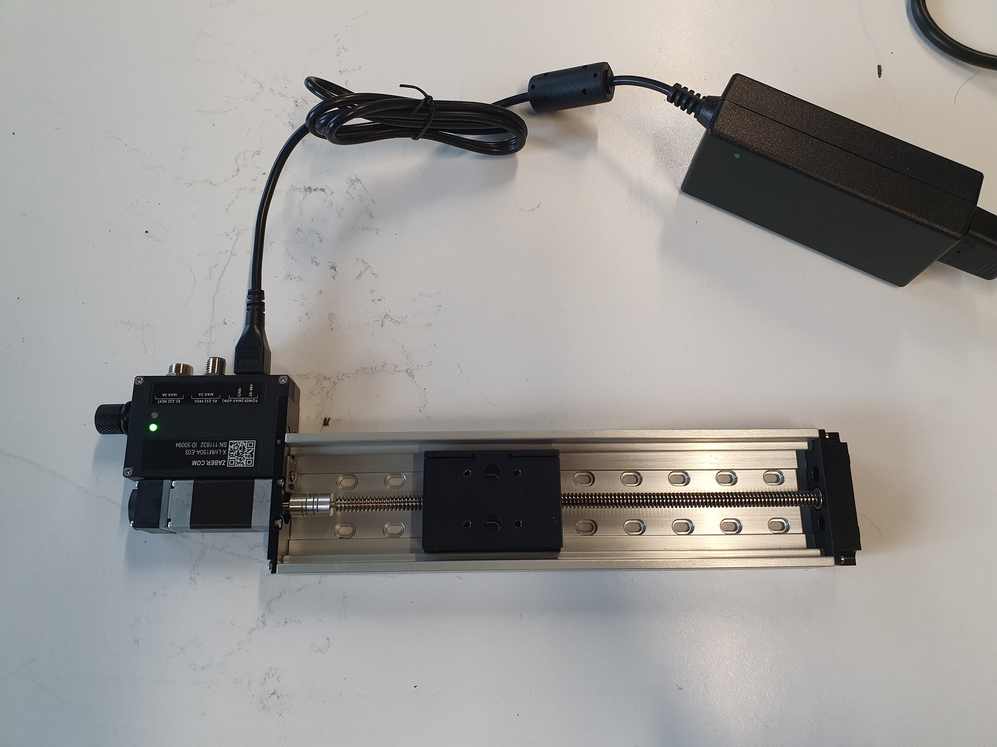
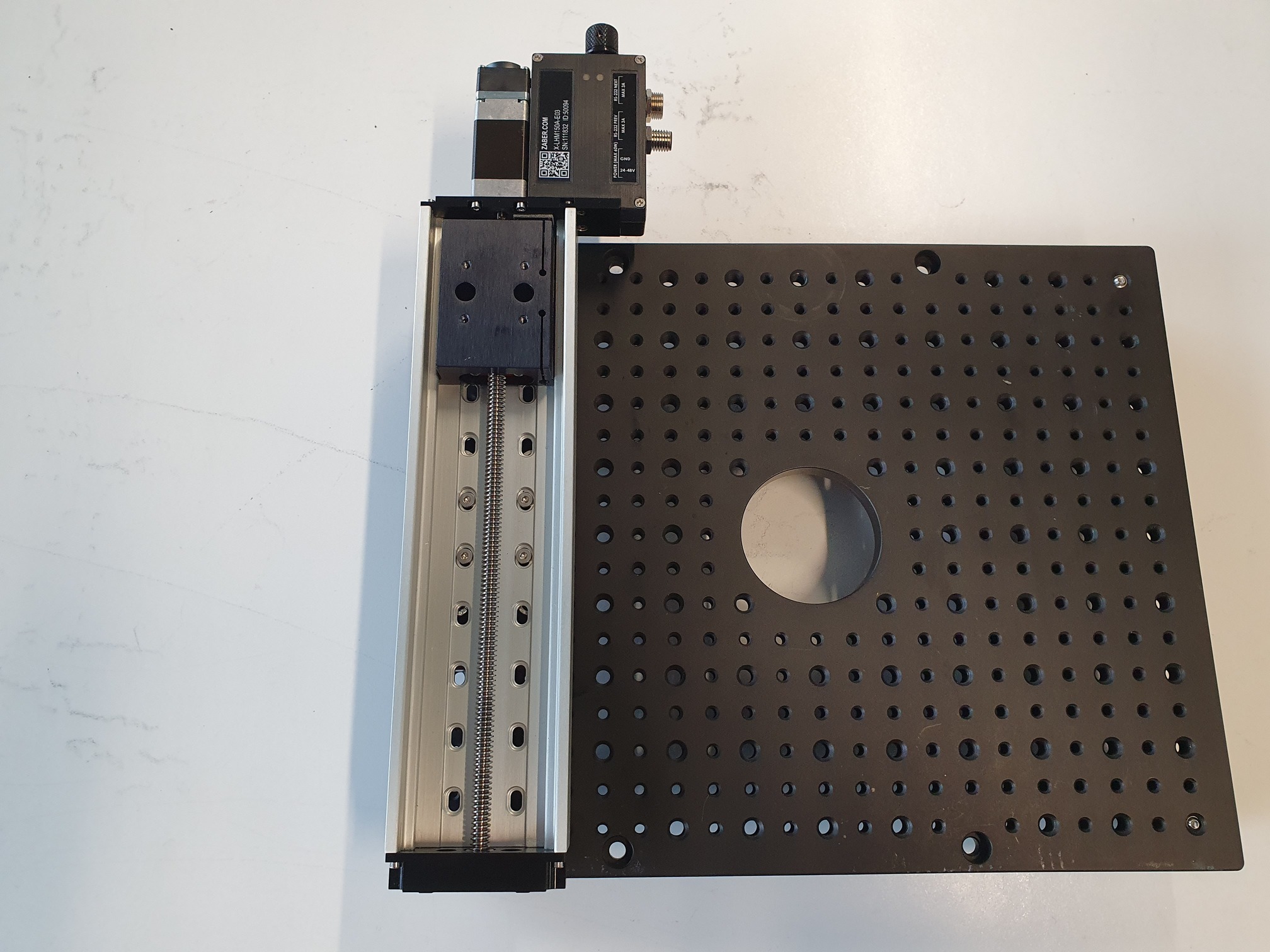
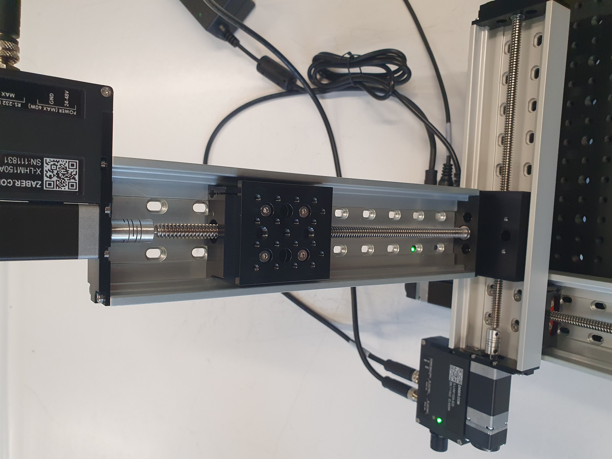
Stage and base
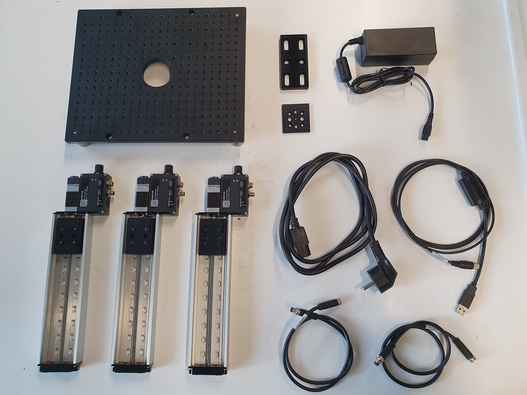 | 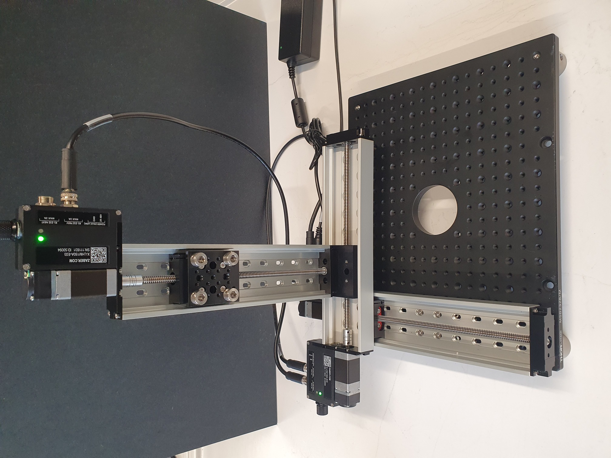 |
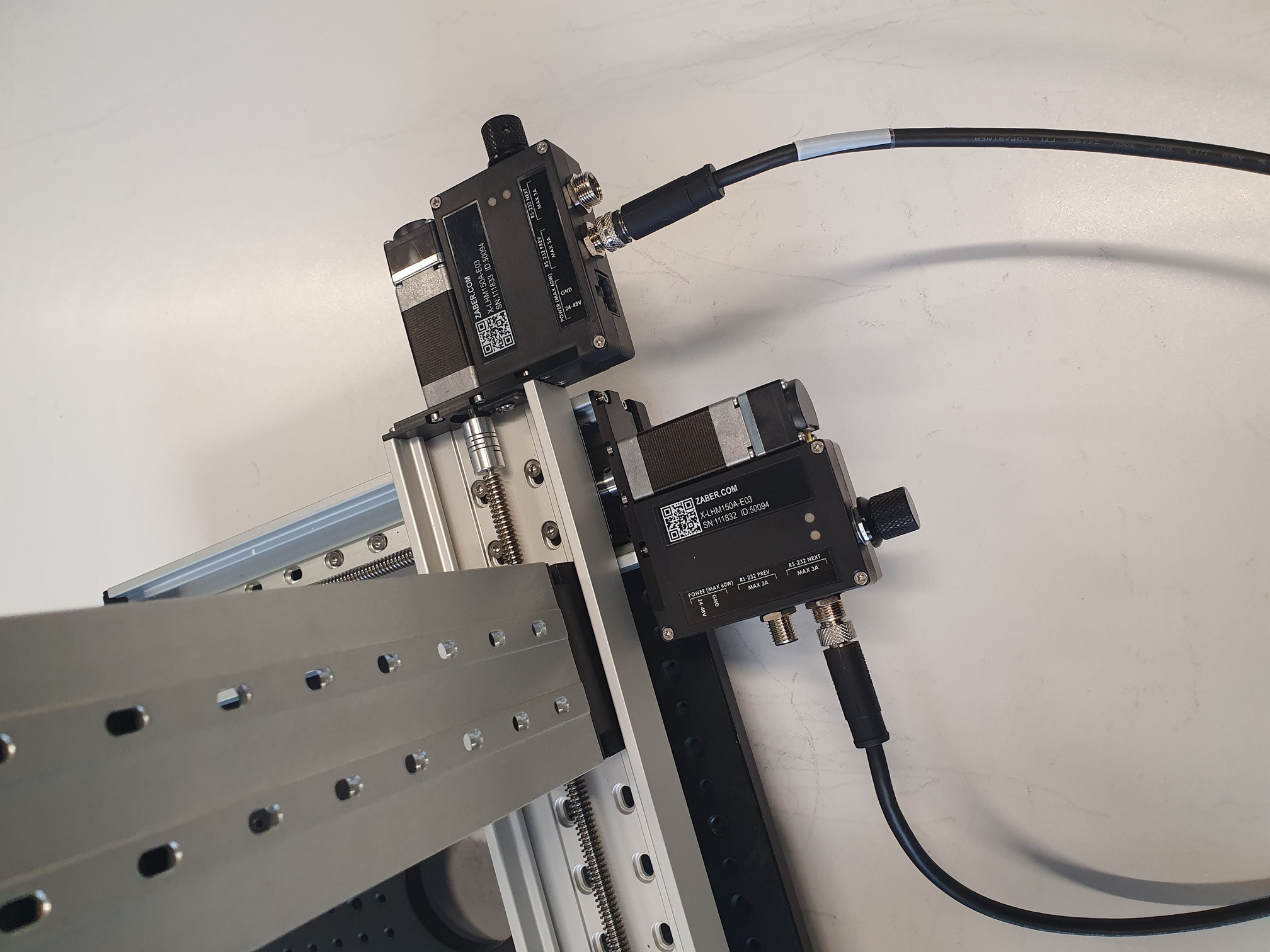
Building the frame
 | 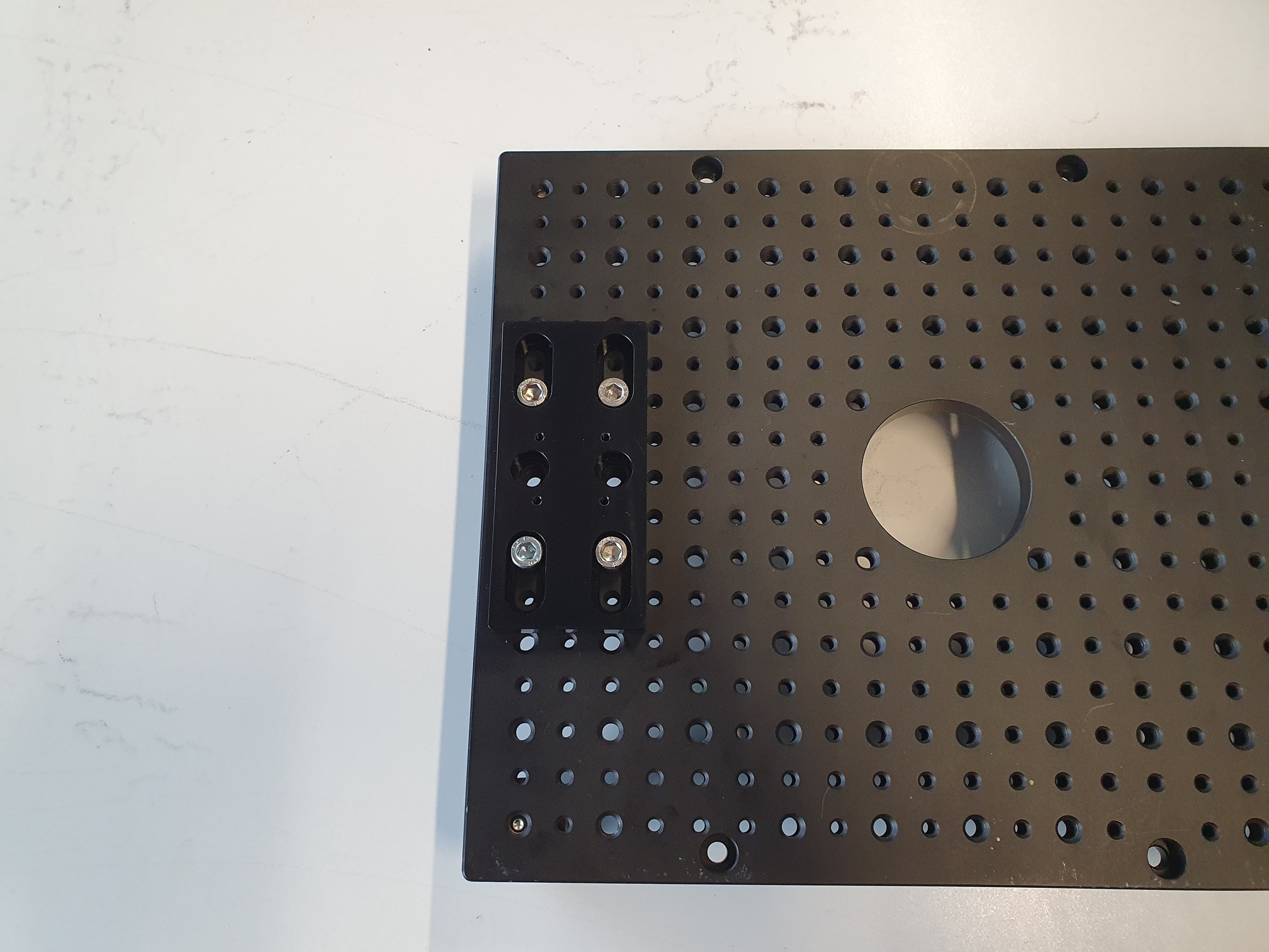 |  |  |
 | 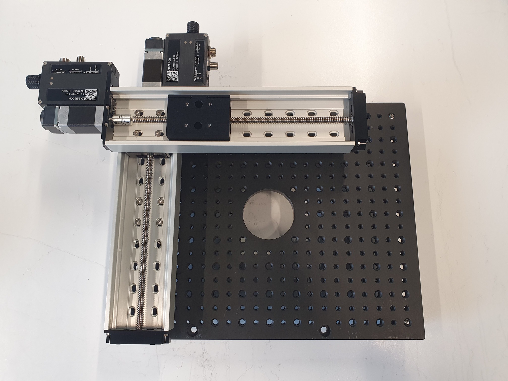 | 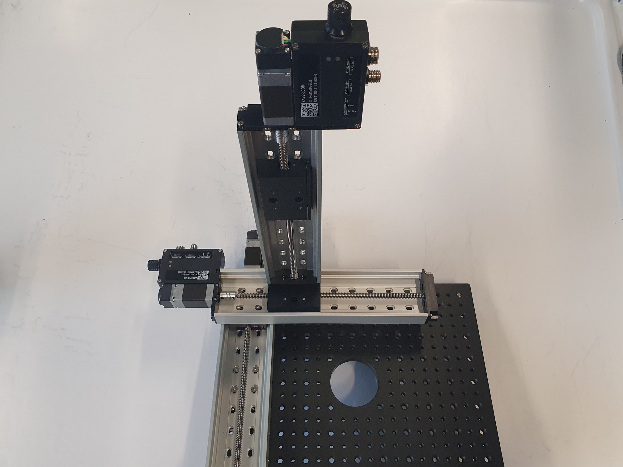 |  |
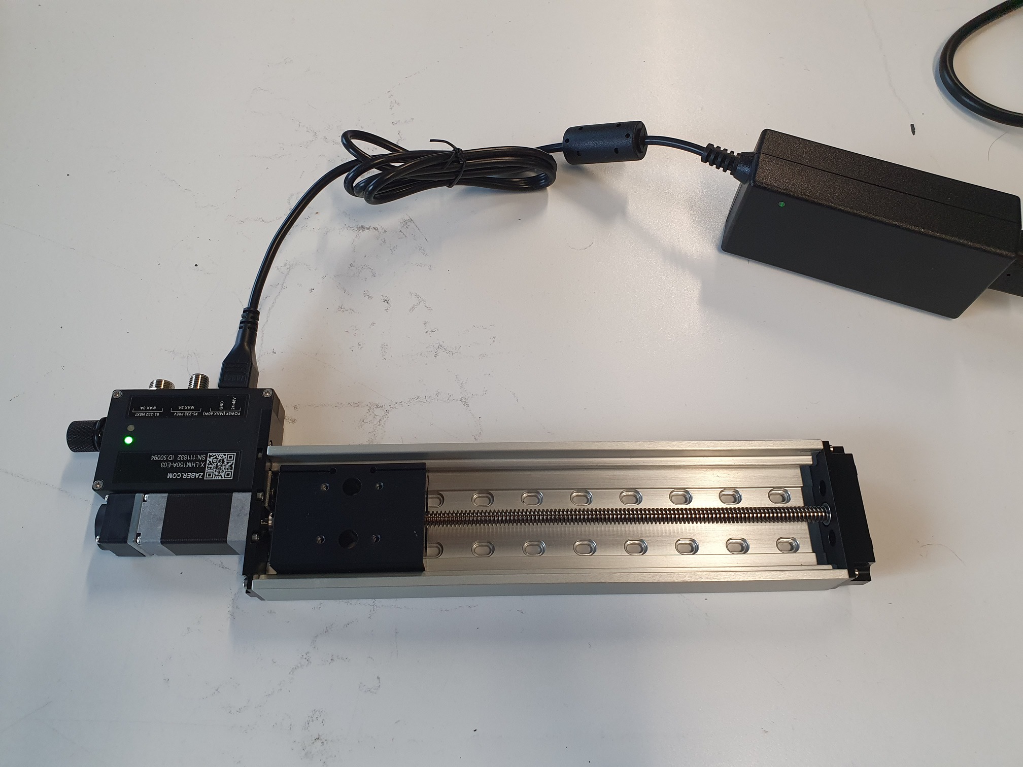
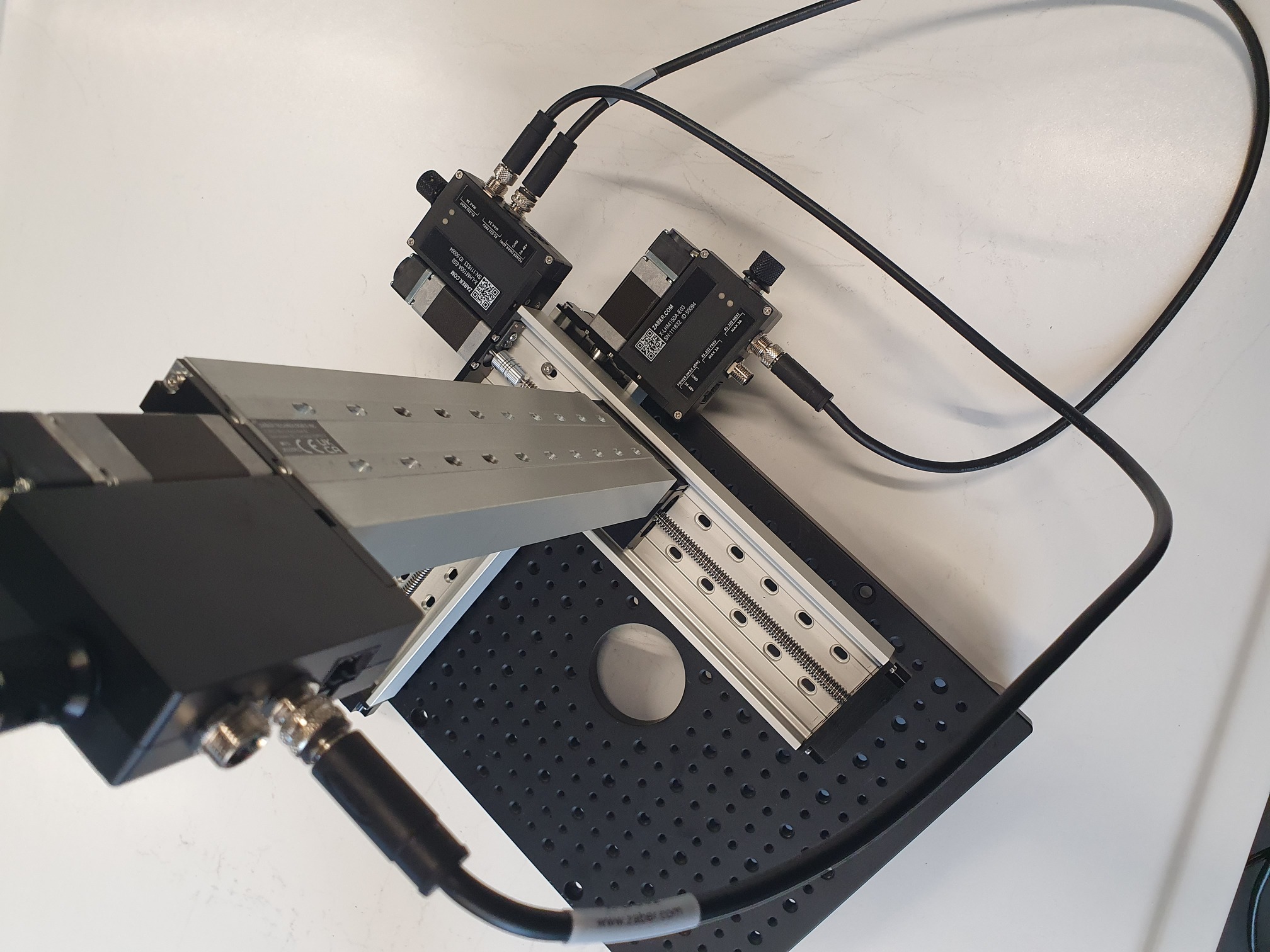
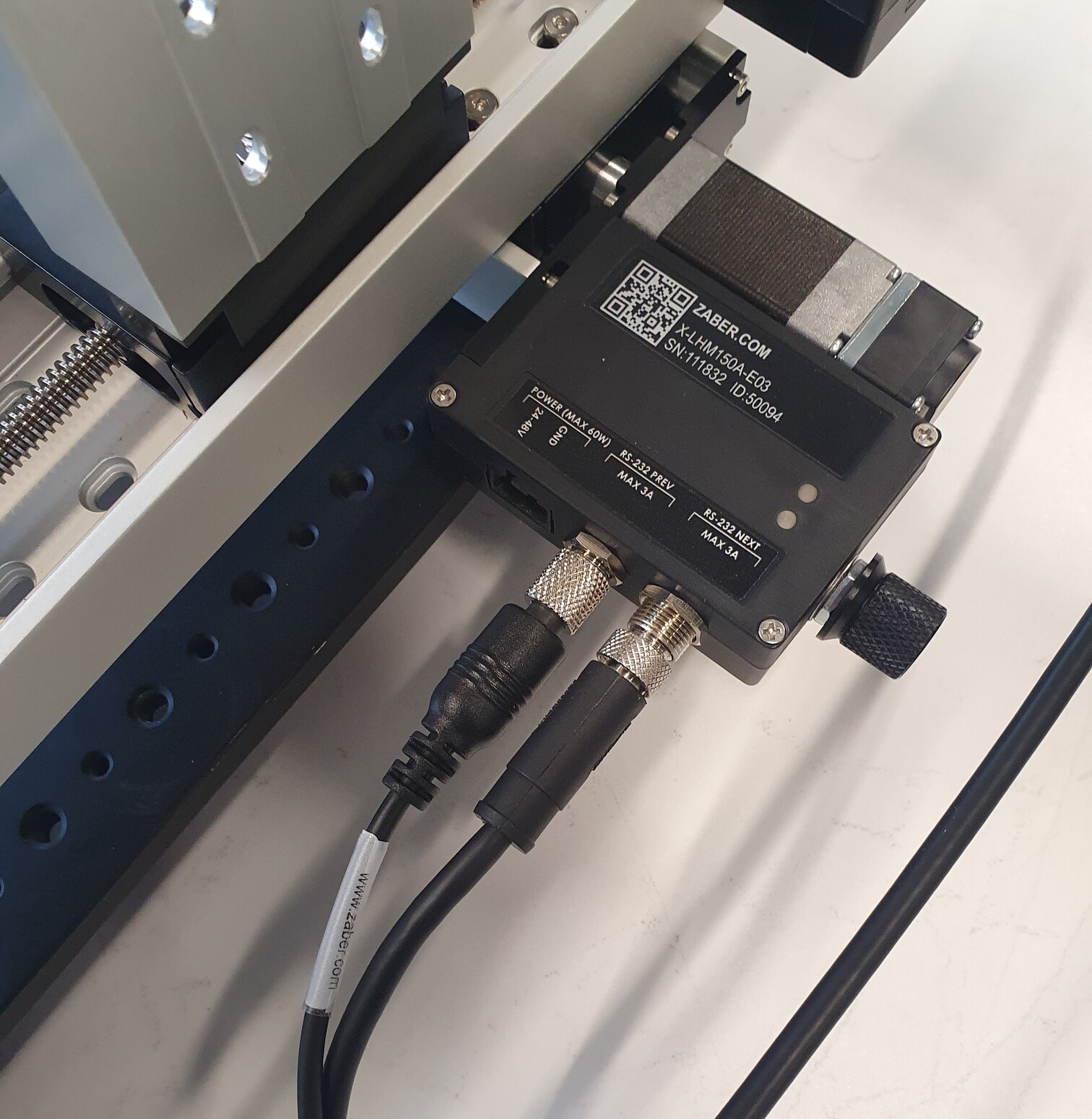
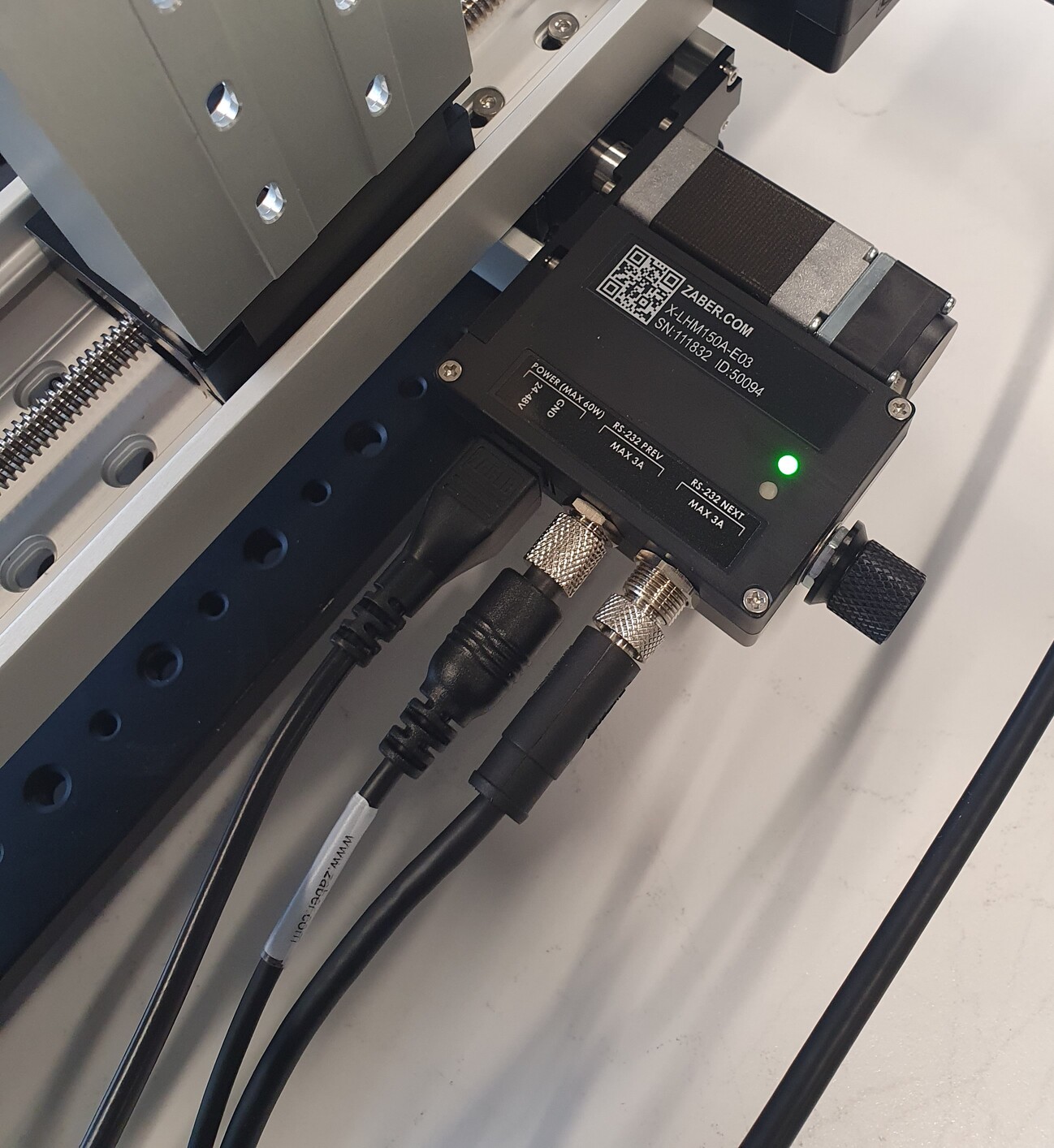
Daisy-chaining the stage
 |  |  |  |
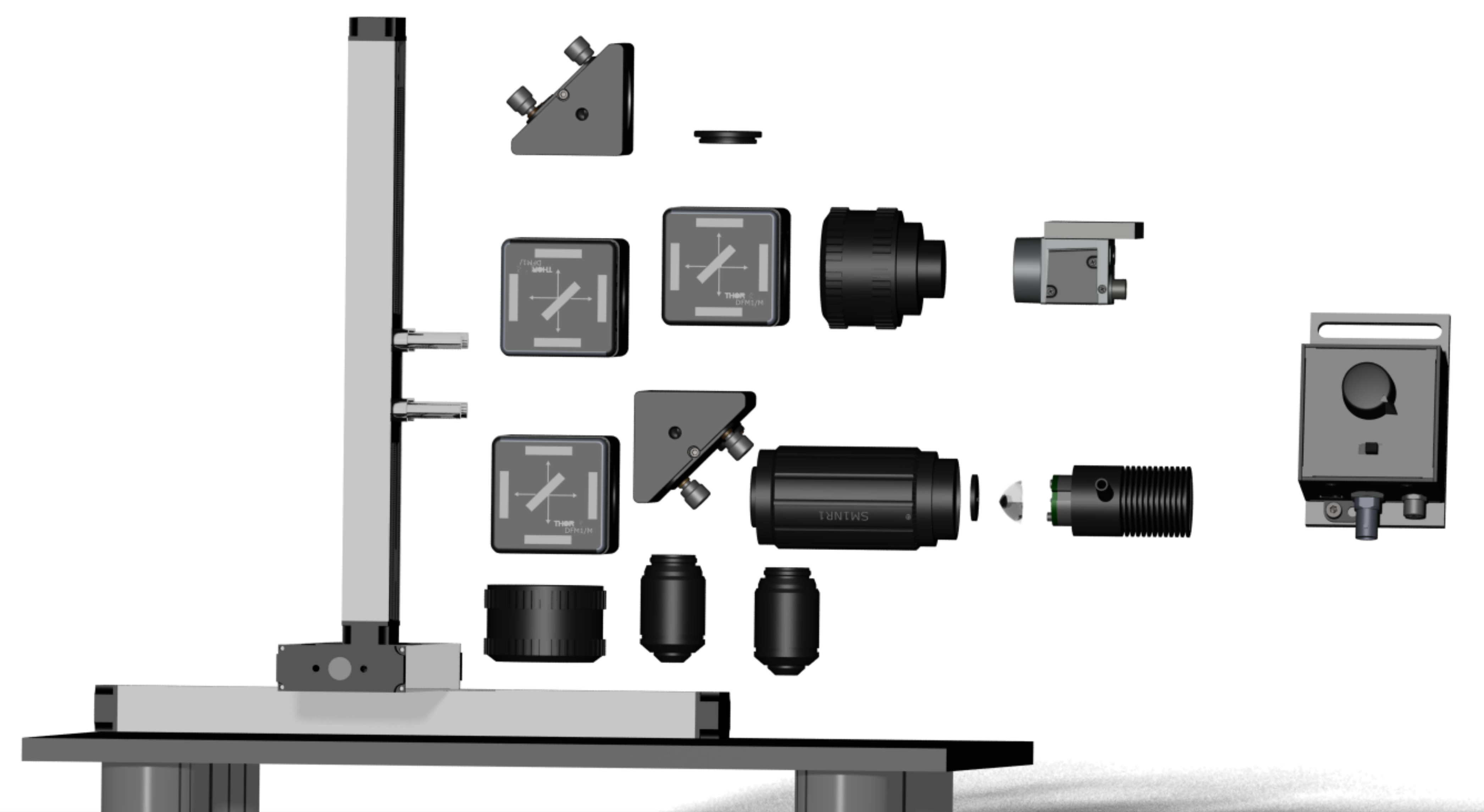
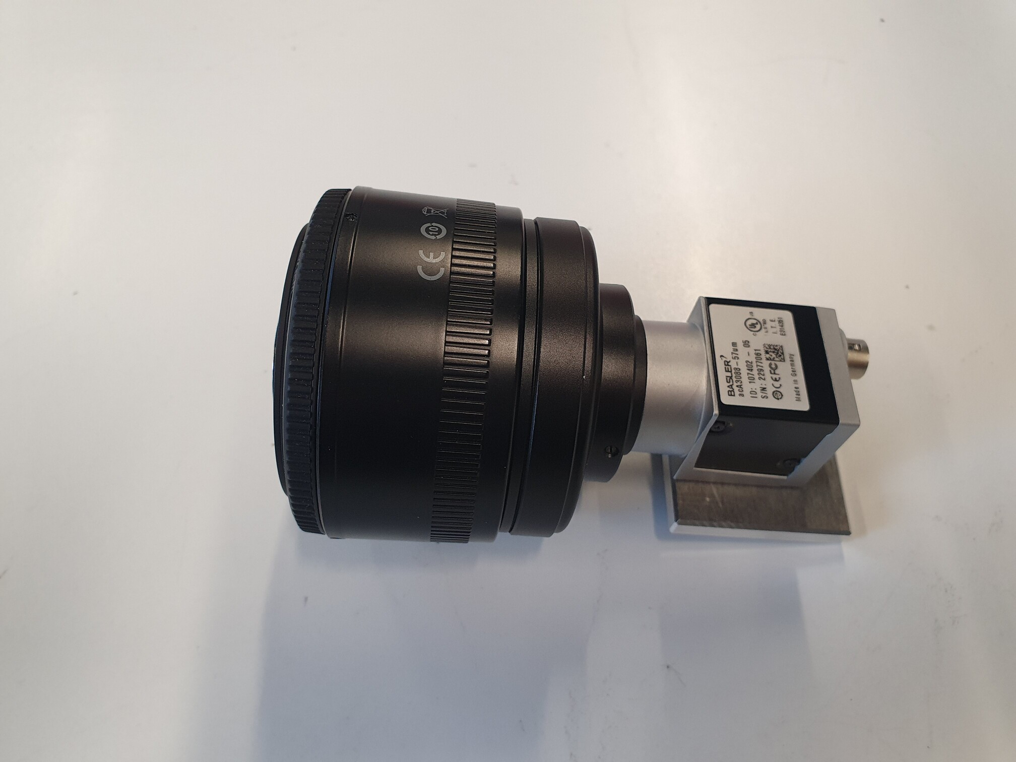
Lightpath - hardware only
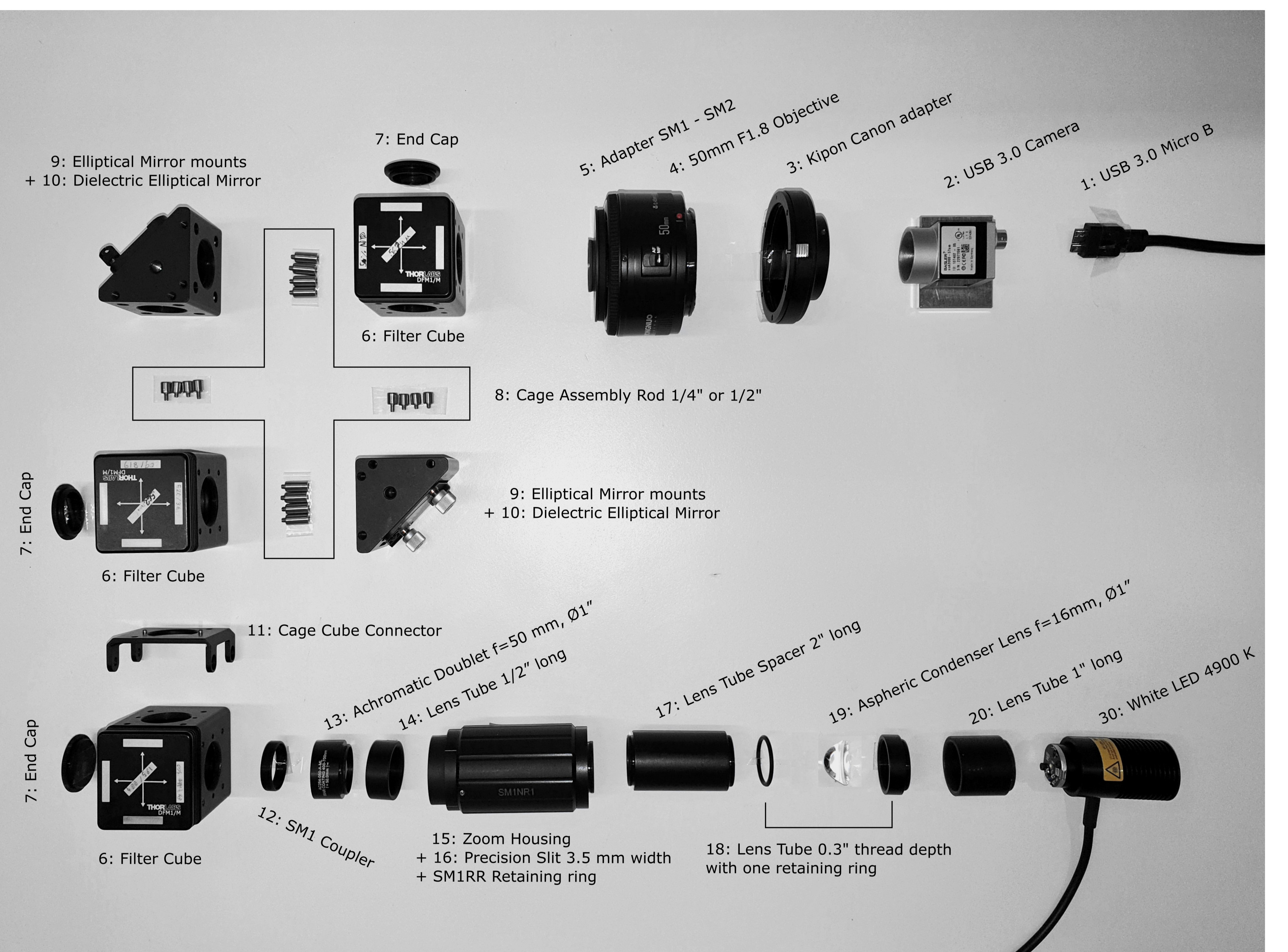
Hardware
In this section, you will add the lightpath to the stages. We will first assemble the structure and add the filters and dichroics in the next step.
Note: If you order the lenses we suggest, they come pre-mounted. However, in case you are using lenses you already have you need to mount them in a short (10 mm) lens tube using a retaining ring. Refer to the lightpath diagram and the photos for correct lens orientation.
 |  |
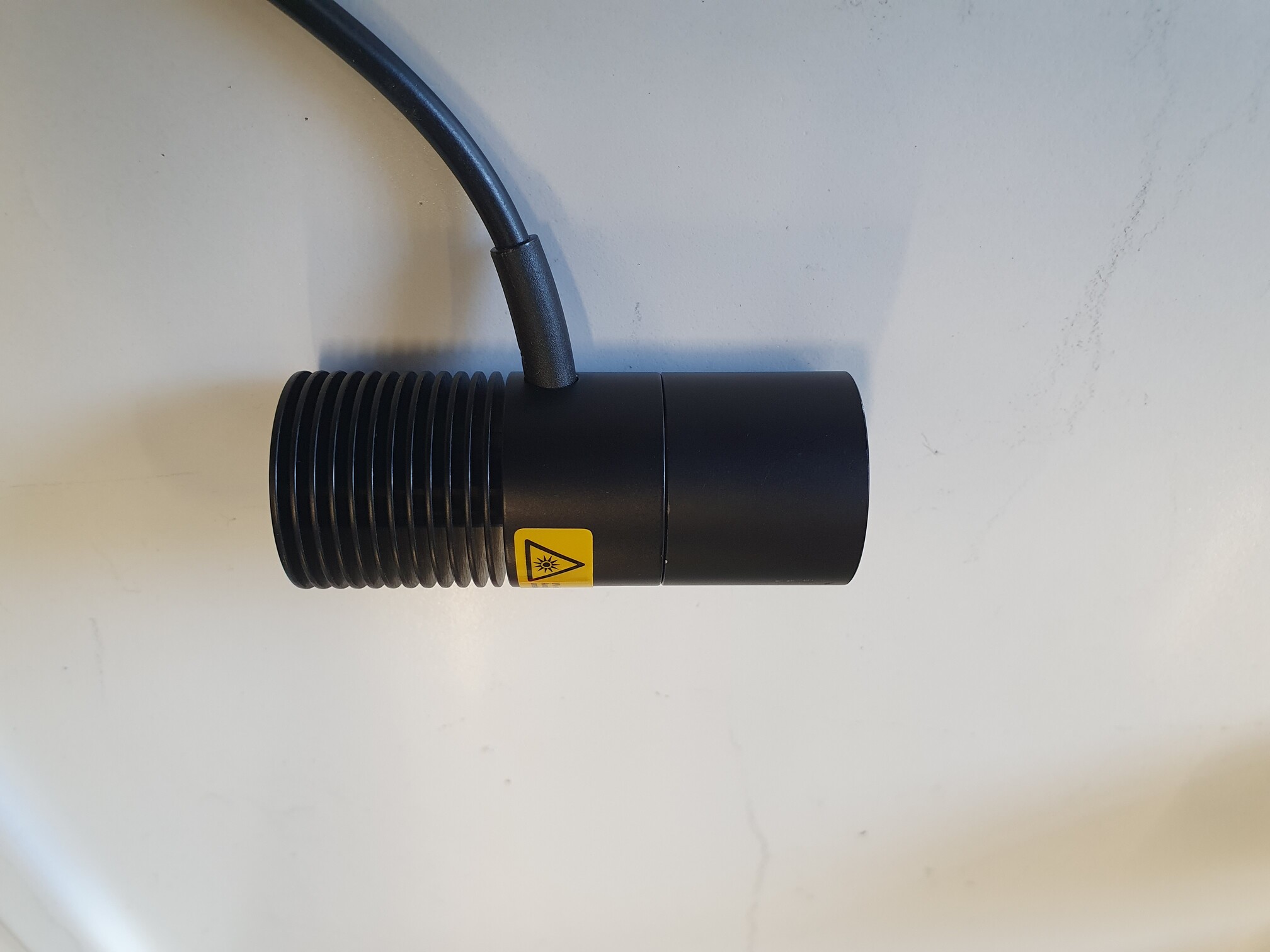
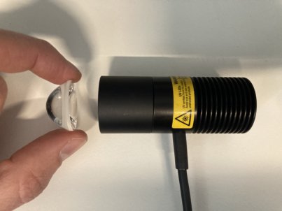
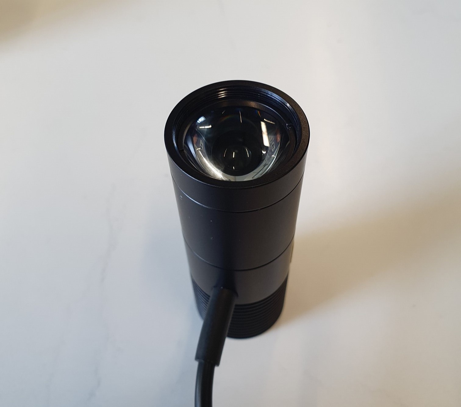
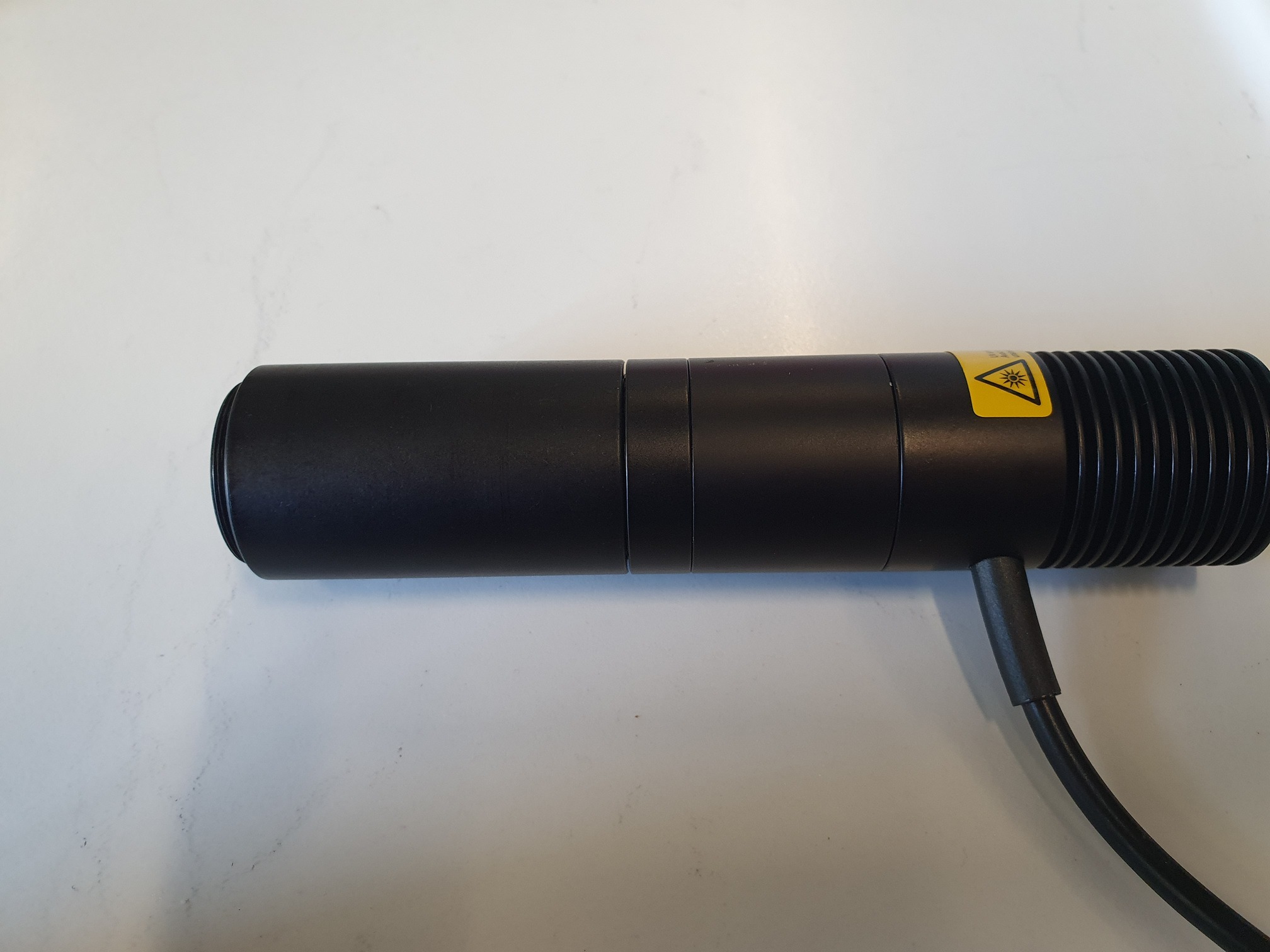
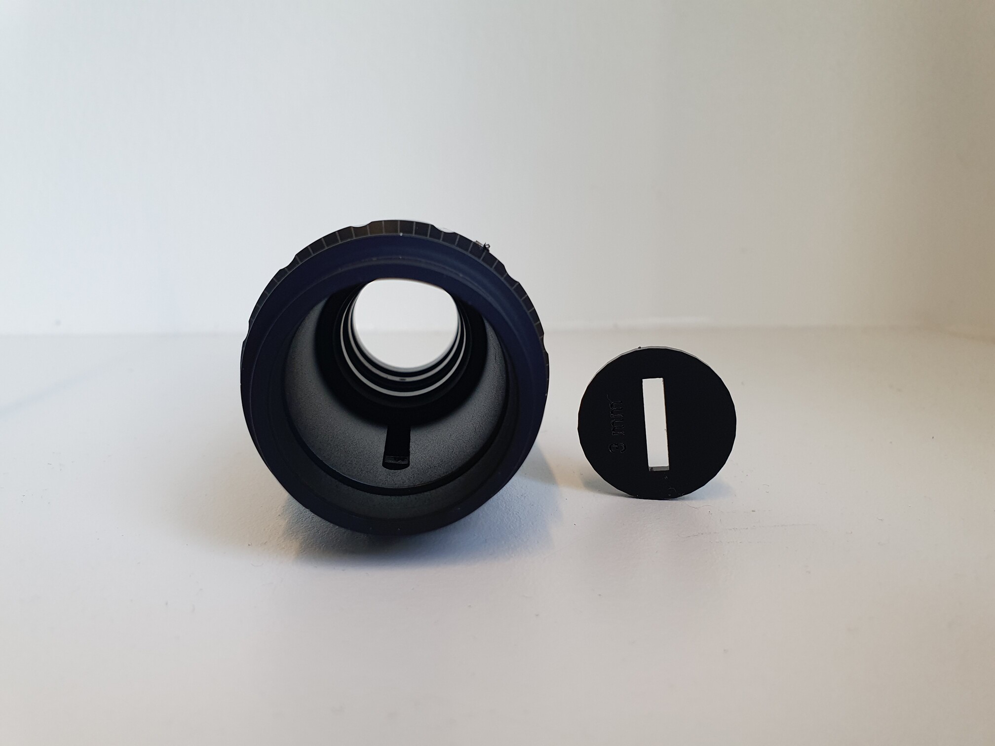
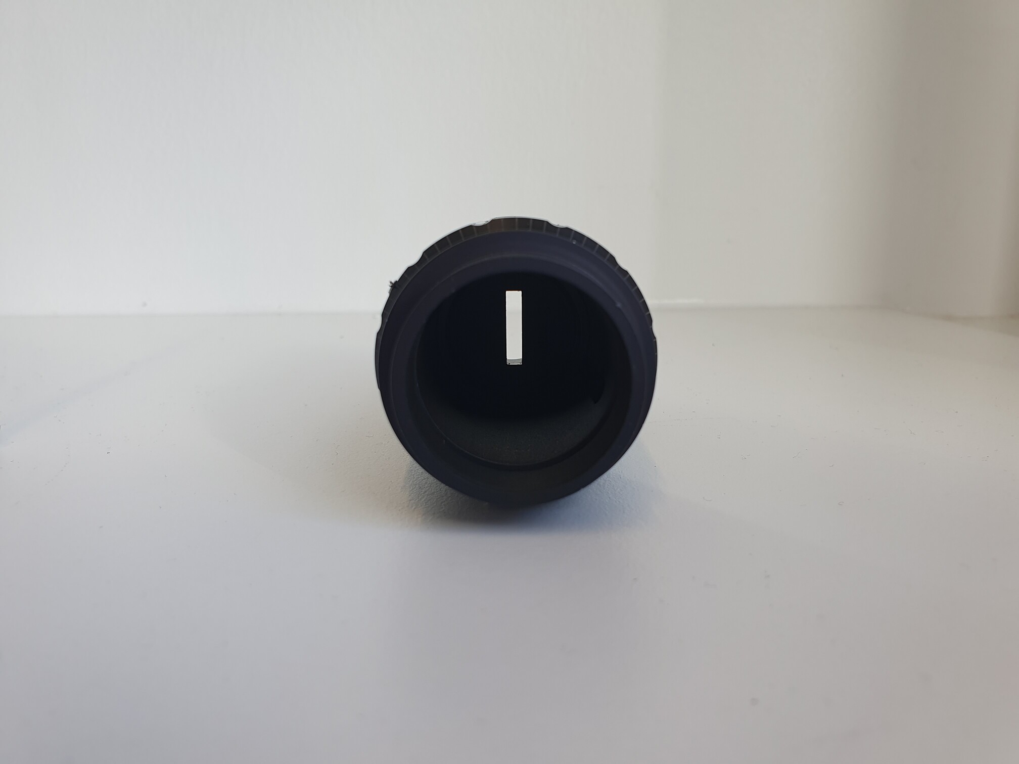
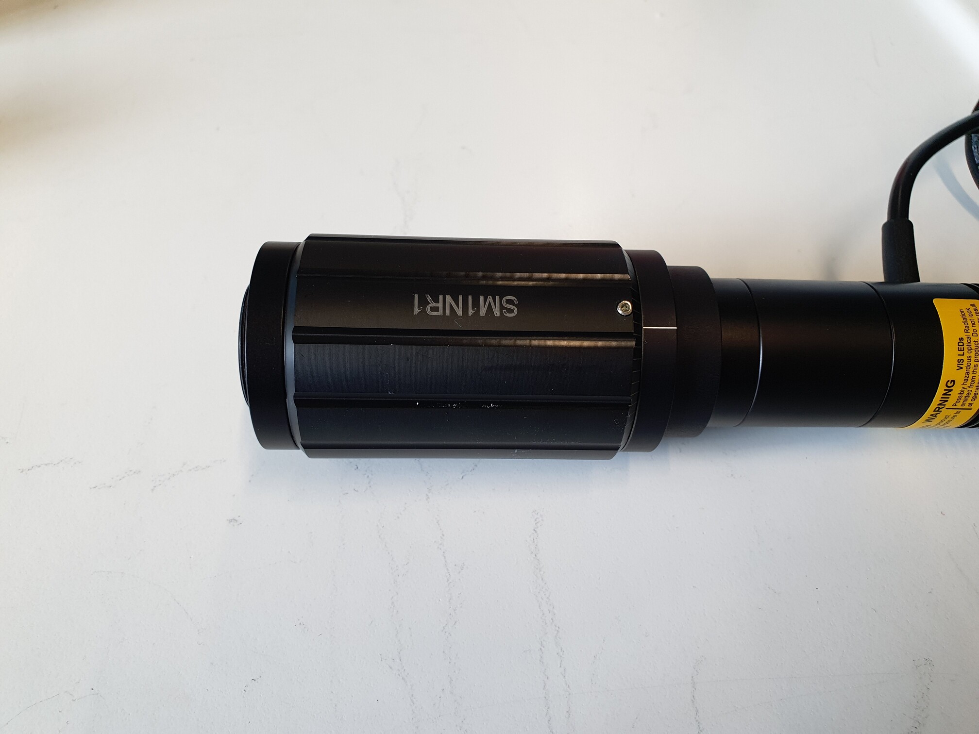
LED assembly
In this section, we assemble the white light LED. The optics are used to collimate the light and focus a slit onto the focal plane of the sample, restricting illumination to a small area. This will allow us to later separate the two colors onto the camera chip.
 |  |  |  |
 |  |  |  |
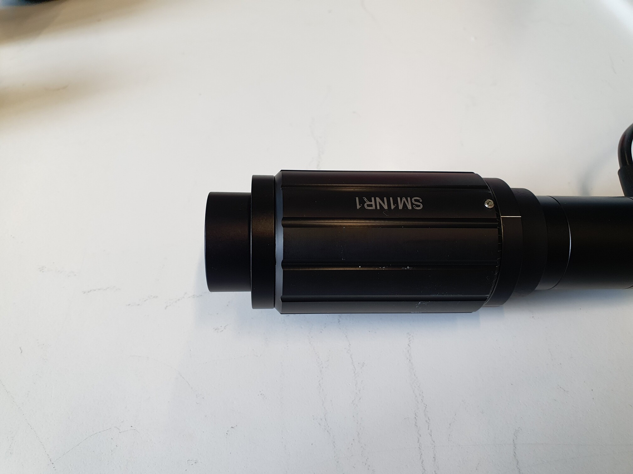 | 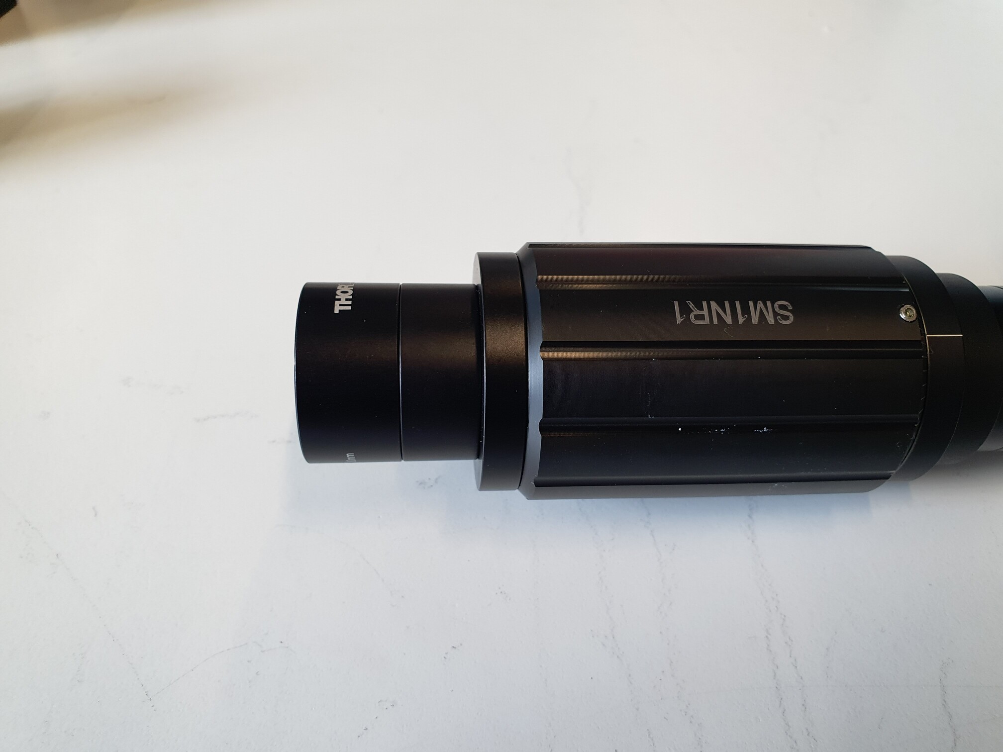 | 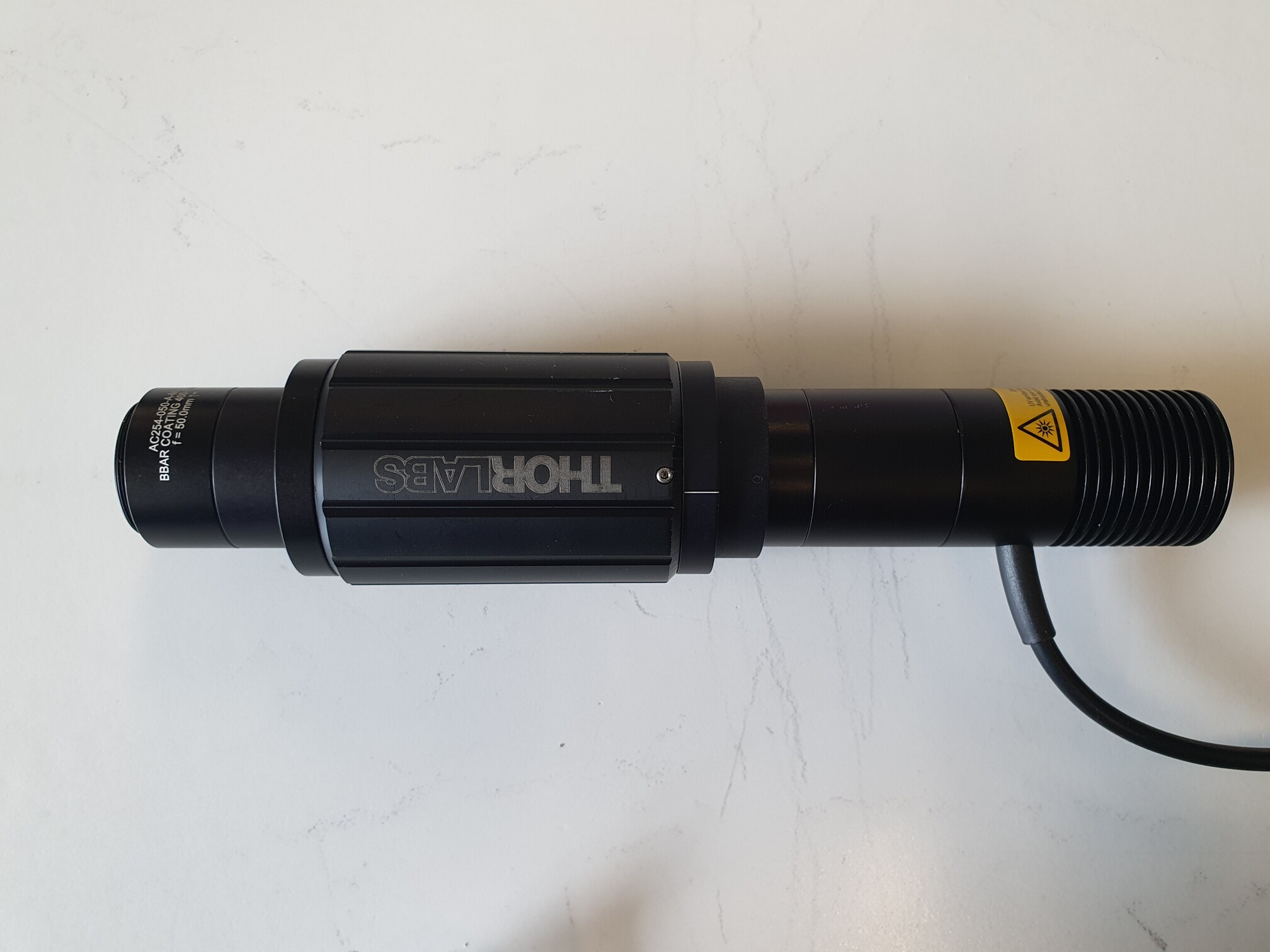 |
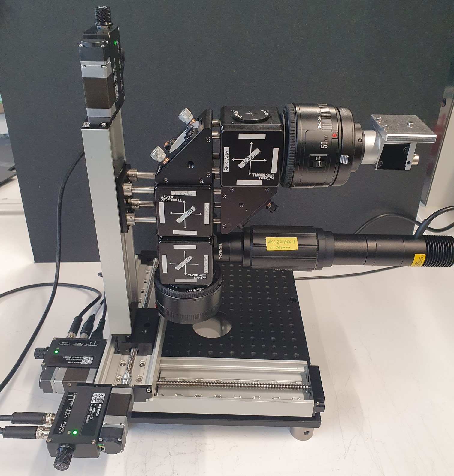
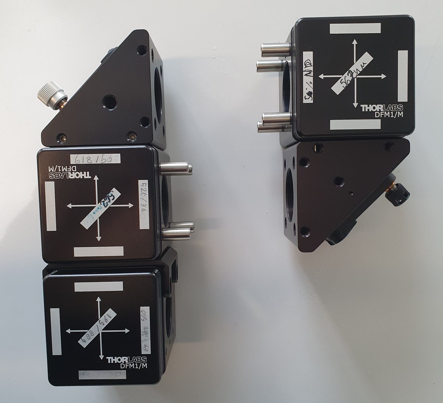
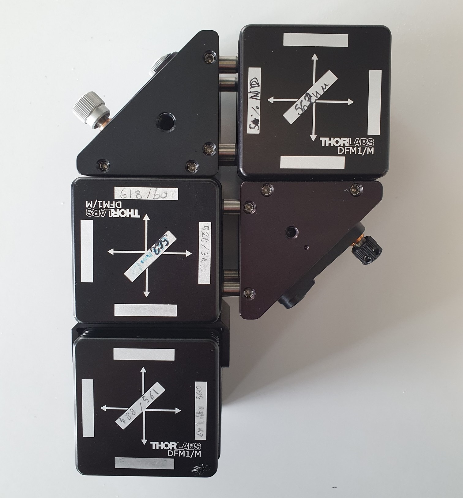
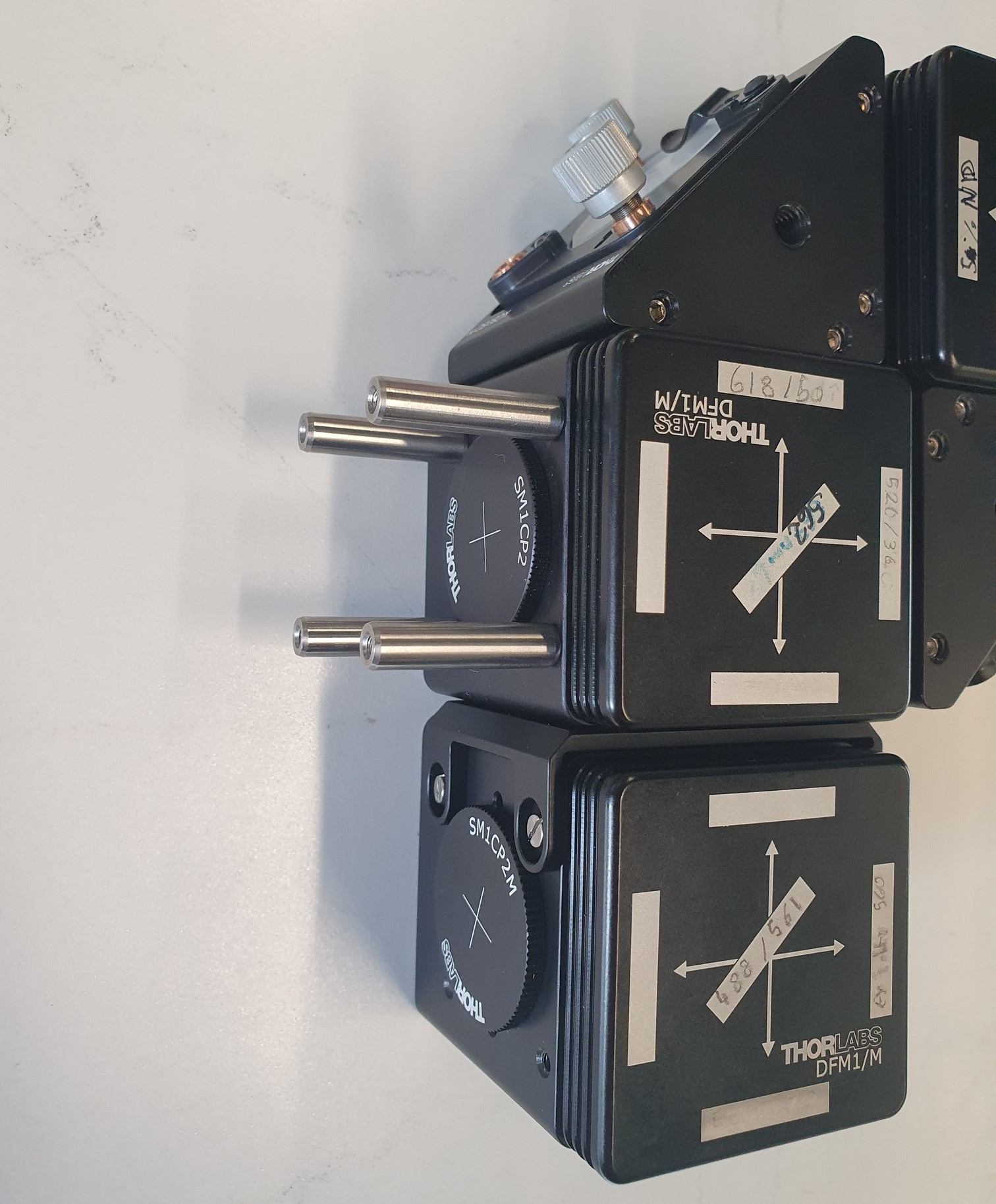
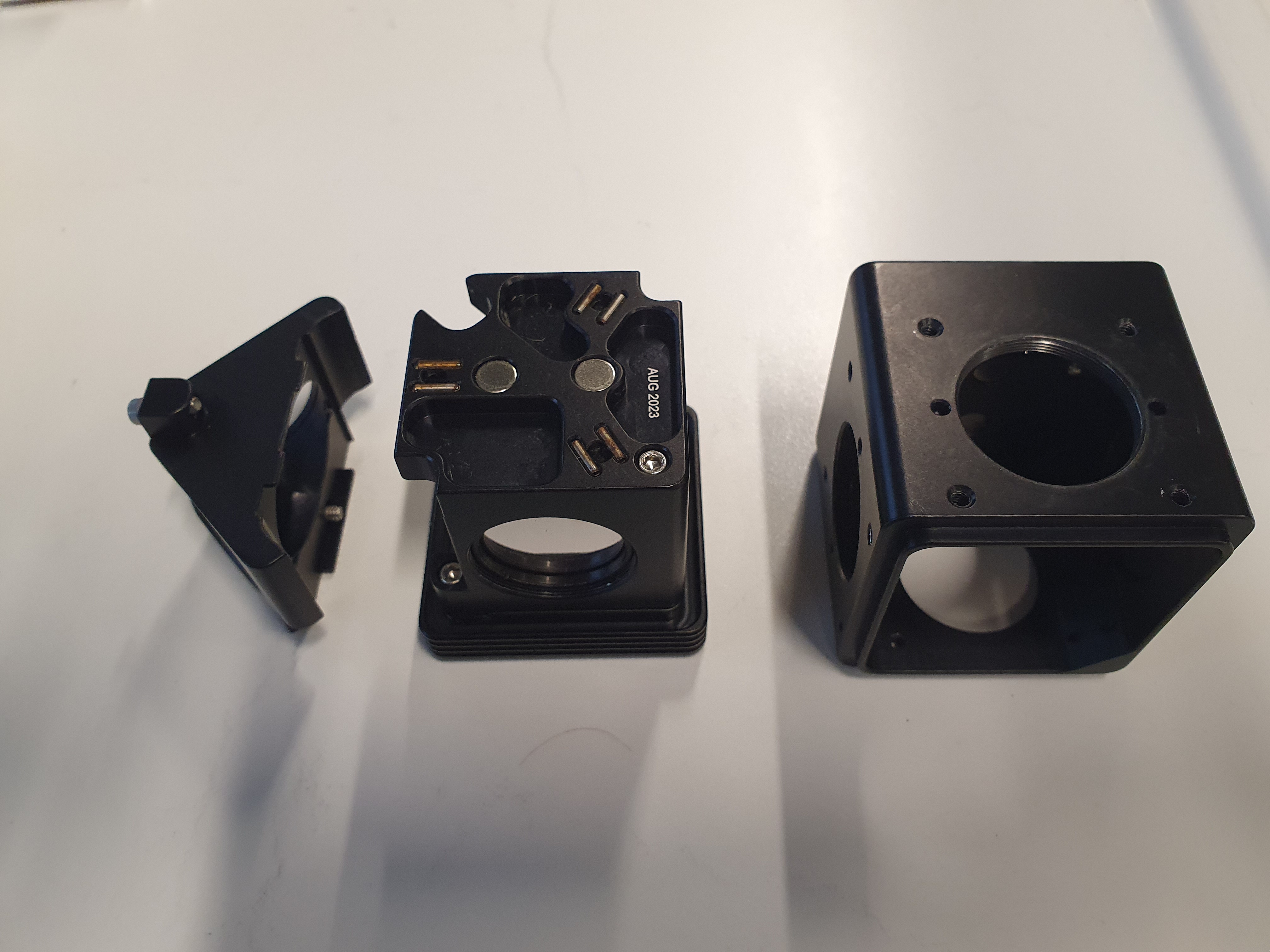
Image-splitter assembly
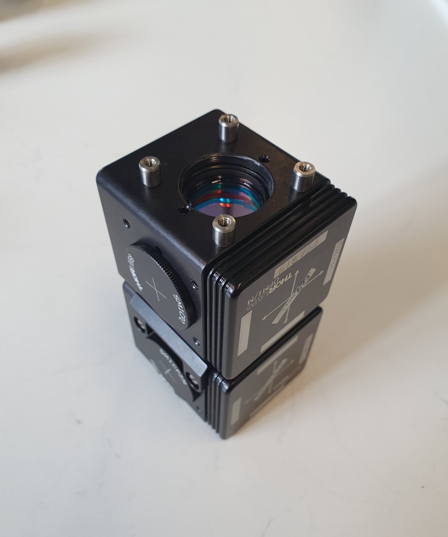
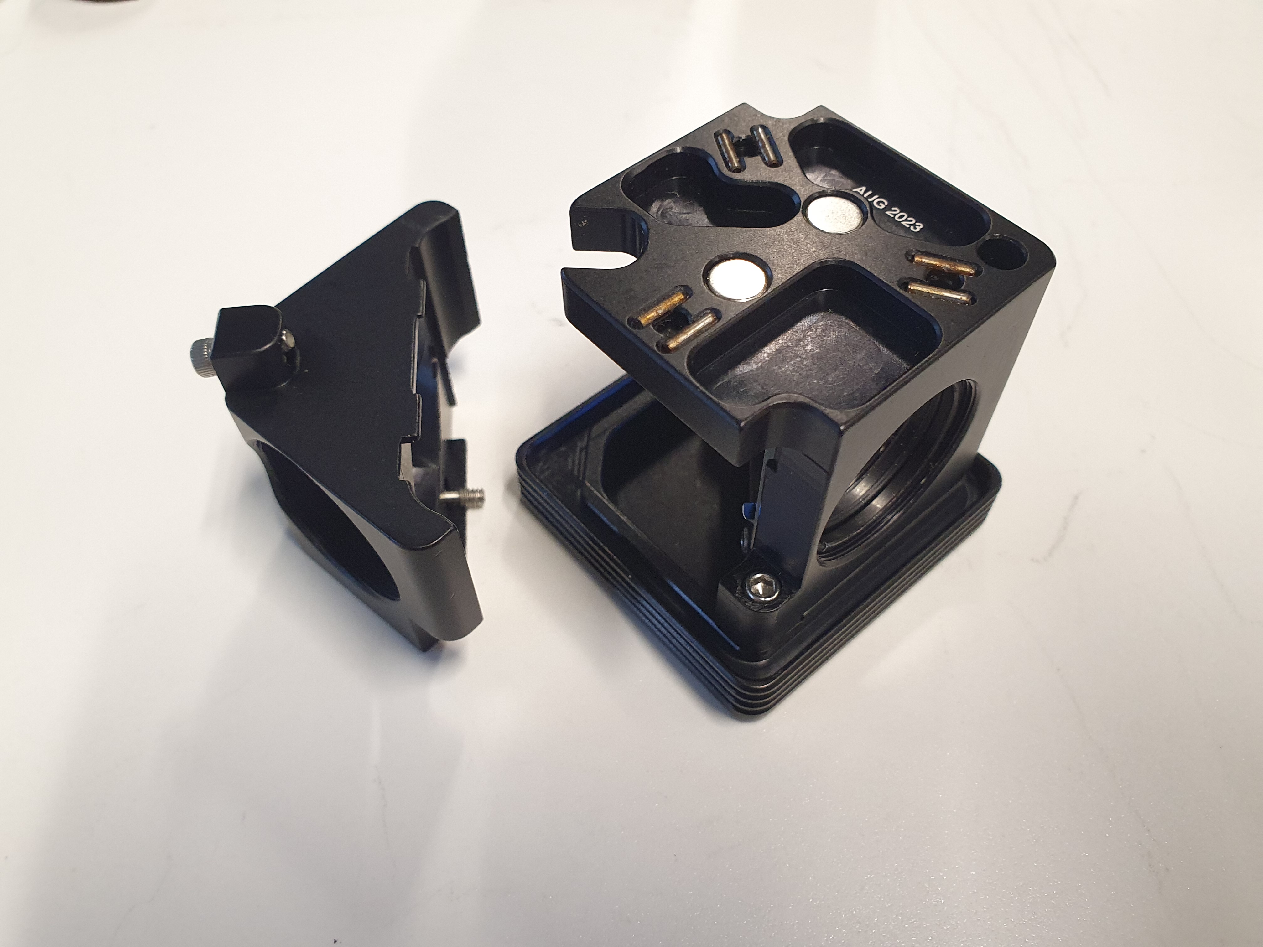
The image splitter is the heart of the microscope. Mechanics matter as a crooked assembly will lead to issues with the image quality. Before starting, please install the GlowTracker application , lay out all the parts required. Pay attention to the cube orientations and follow the pictures exactly.
 |  |  |
 |  |  |
 |  |  |
 |  Insert mirrors into mirror mounts. |  |
Finishing up
 | | |
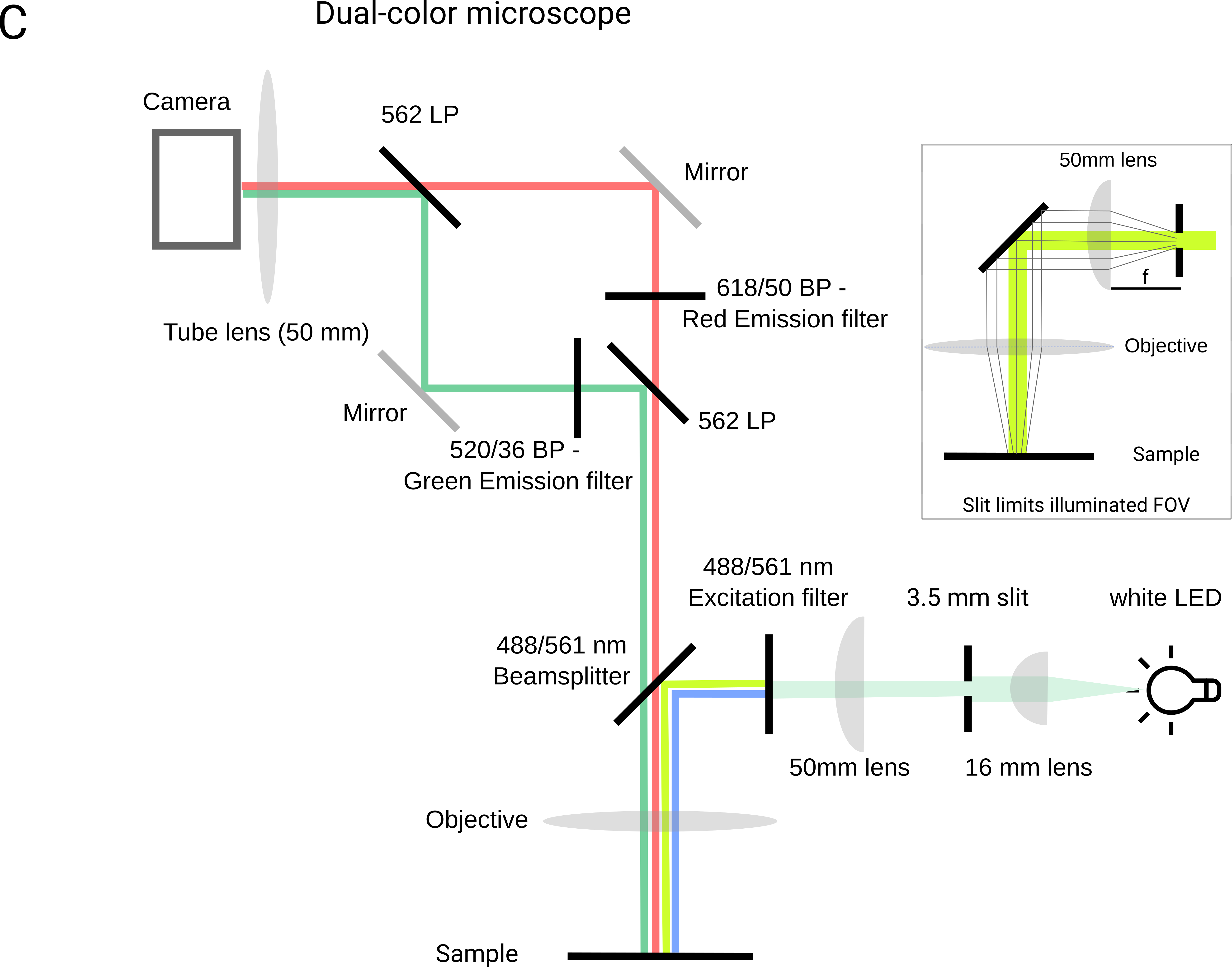
Lightpath - Filters and Dichroics
In this section, you will handle a lot of expensive filters and dichroic mirrors. It is helpful to have optical cleaning supplies handy in case you touch a lens or filter. Always touch optics at the edge, as smudges are hard to remove and will degrade your image quality. Filters and dichroics have a preferred direction, so please pay attention to the orientation you put them in. If your image quality is not ideal, and you see reflections or double images, that may be due to a flipped filter.
The schematic of the filters is shown here:
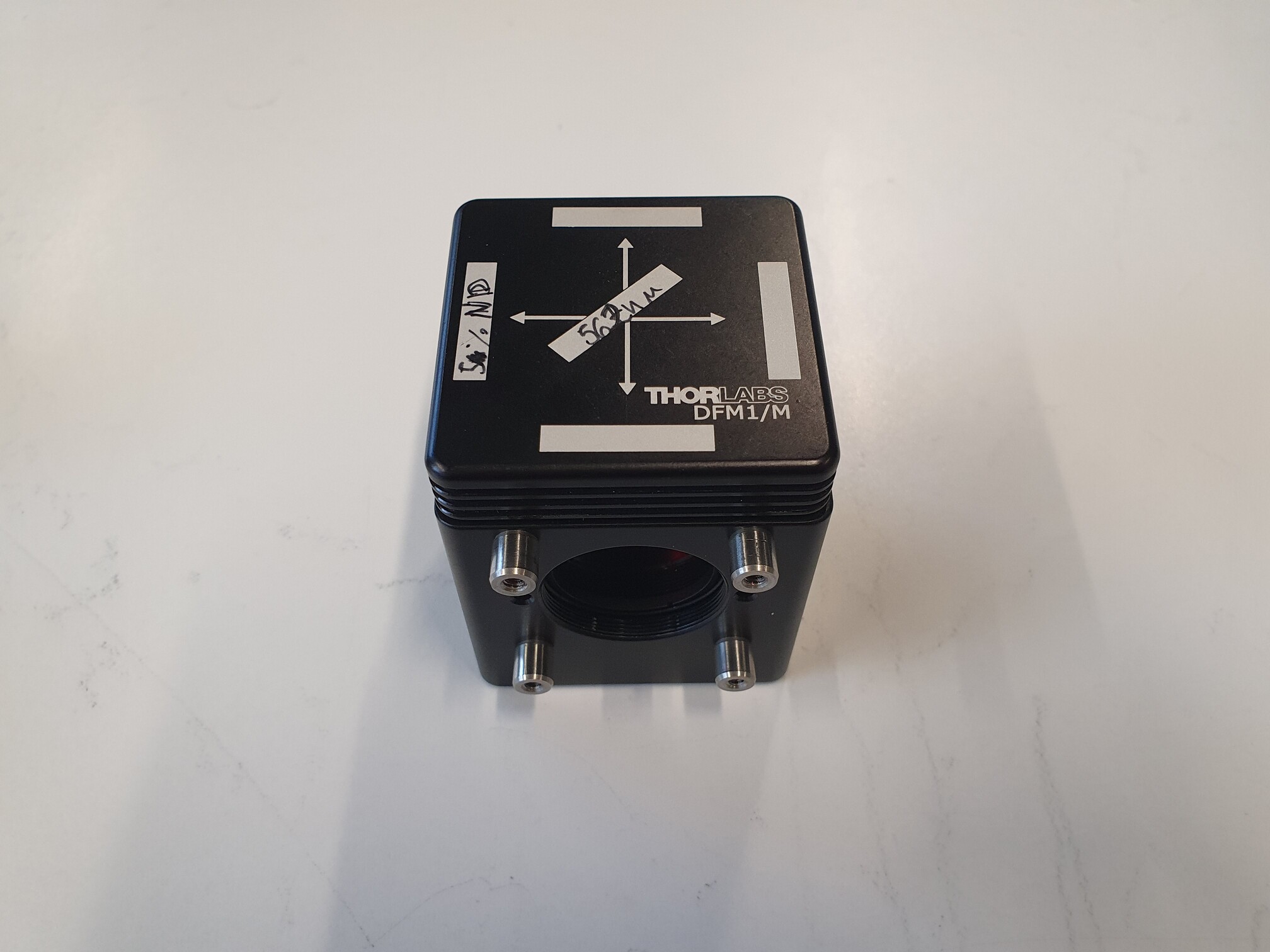
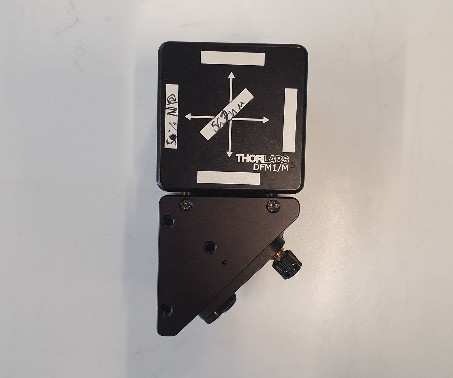
Filter cube 1 - Excitation light
All filters will require similar steps. We will show the full process for the first cube. Repeat for Cubes 2 and 3. A video for instructions can be found here.
For this cube, you will need one 488/561 nm dichroic and a dualband excitation filter 59011x.
| |  |  |
 | 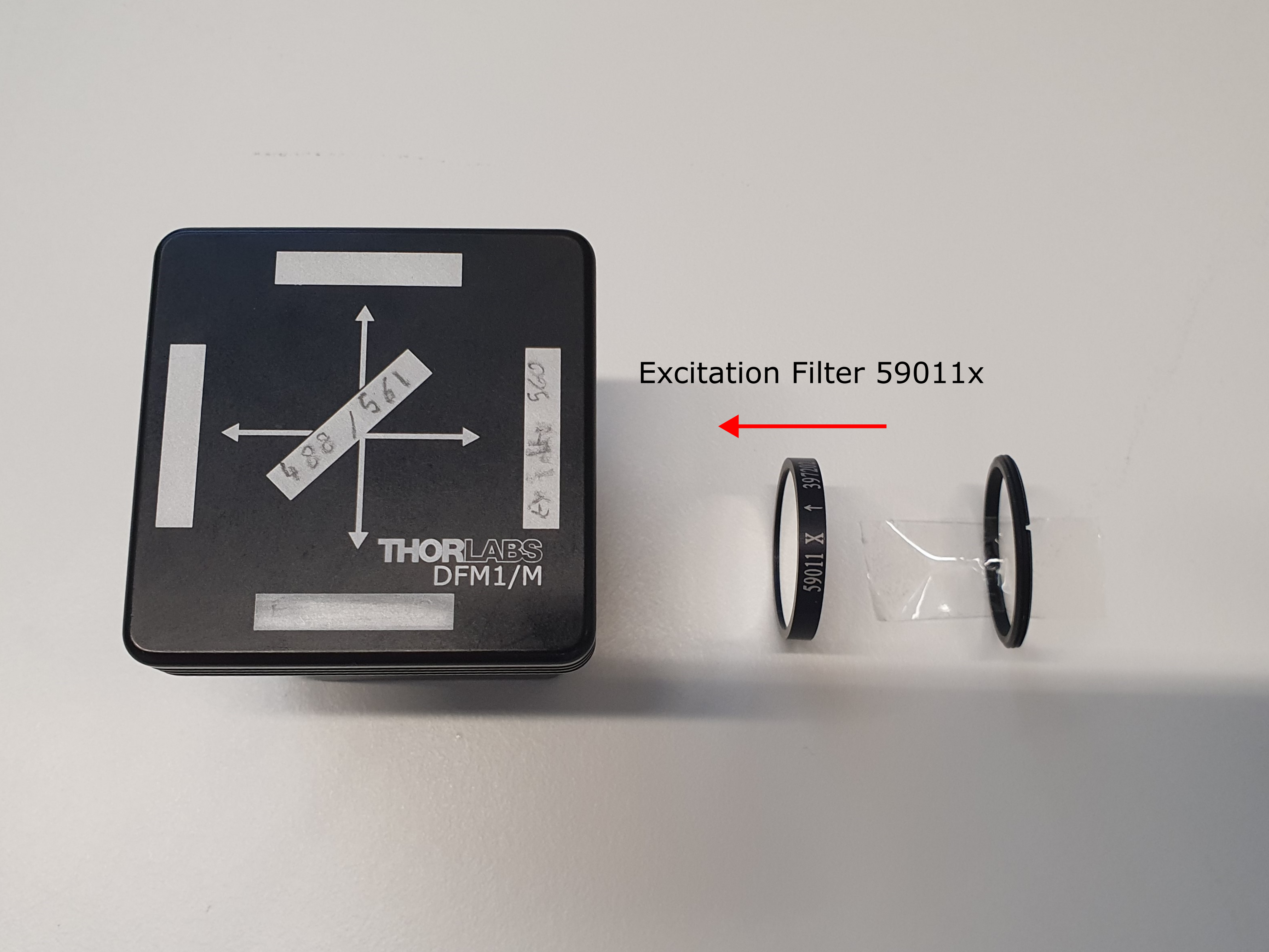 |
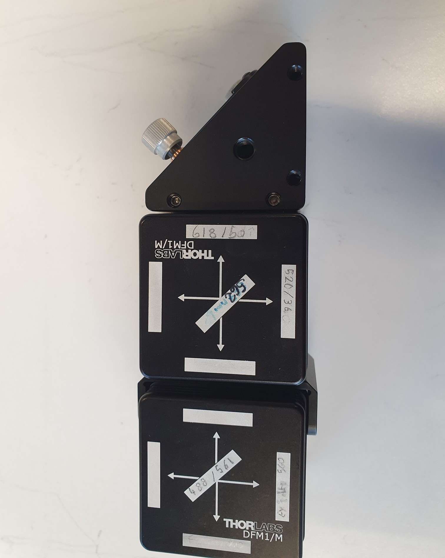
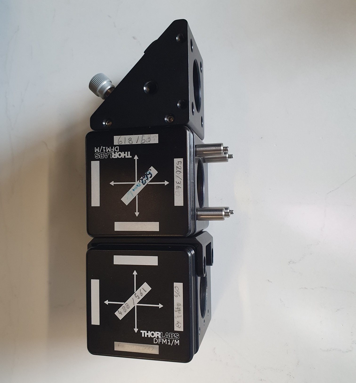
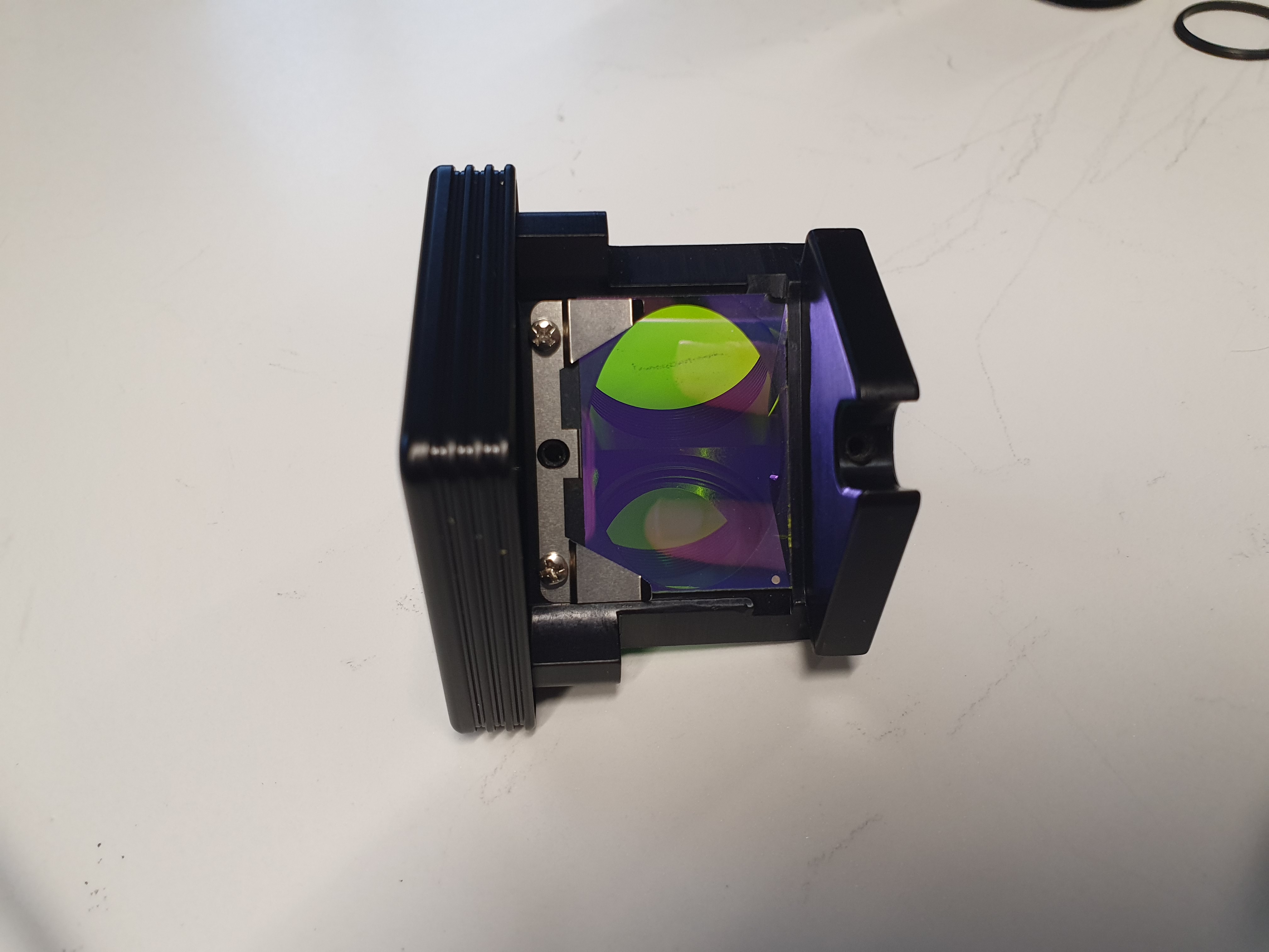
Filter cube 2 - Image splitter cube with emission filters
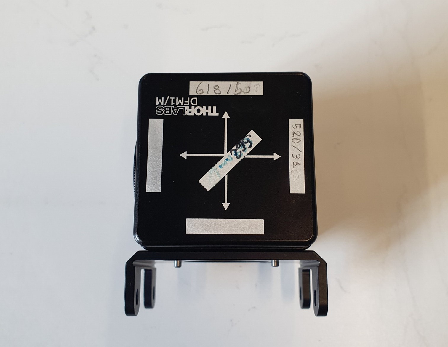
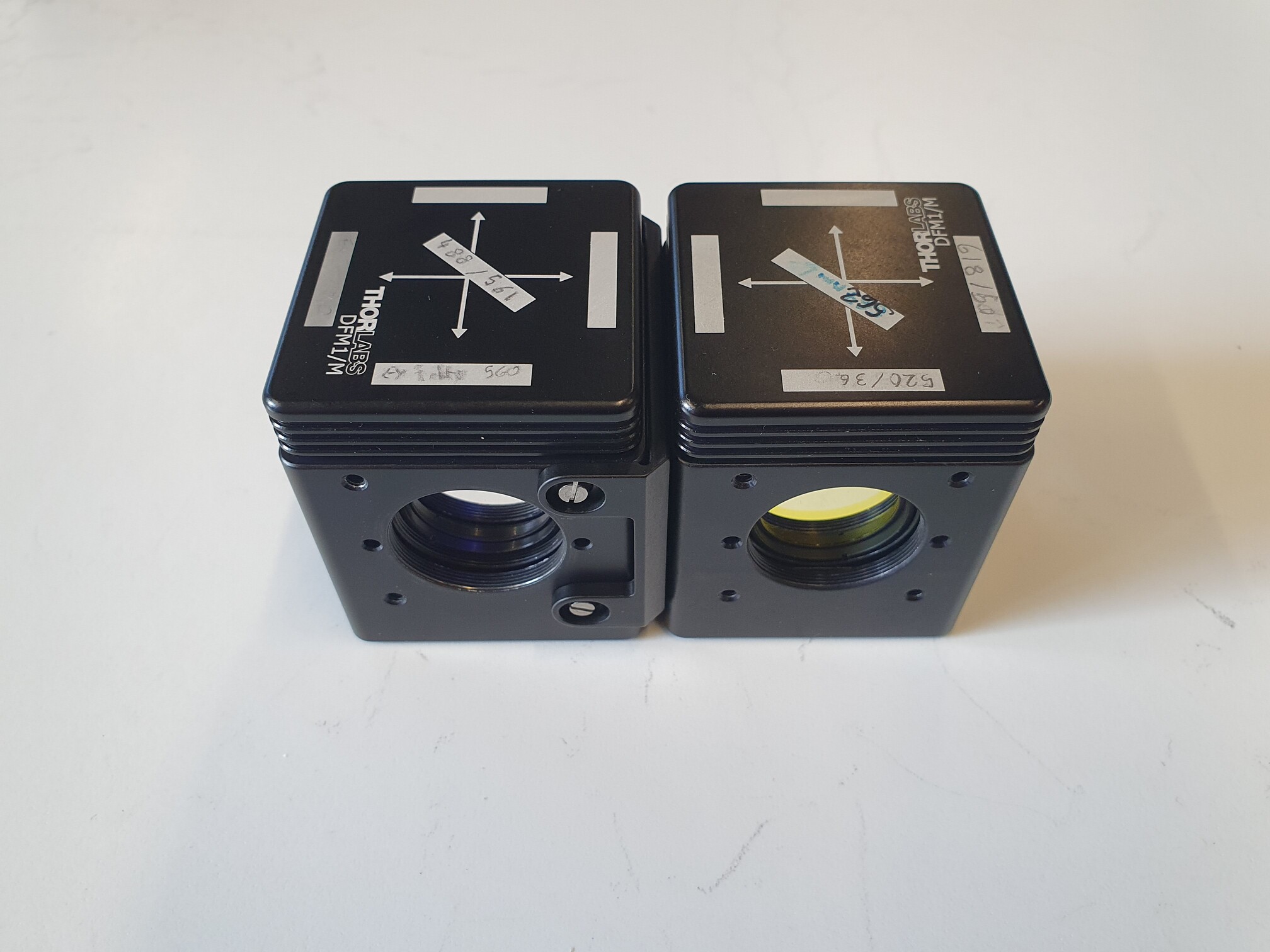
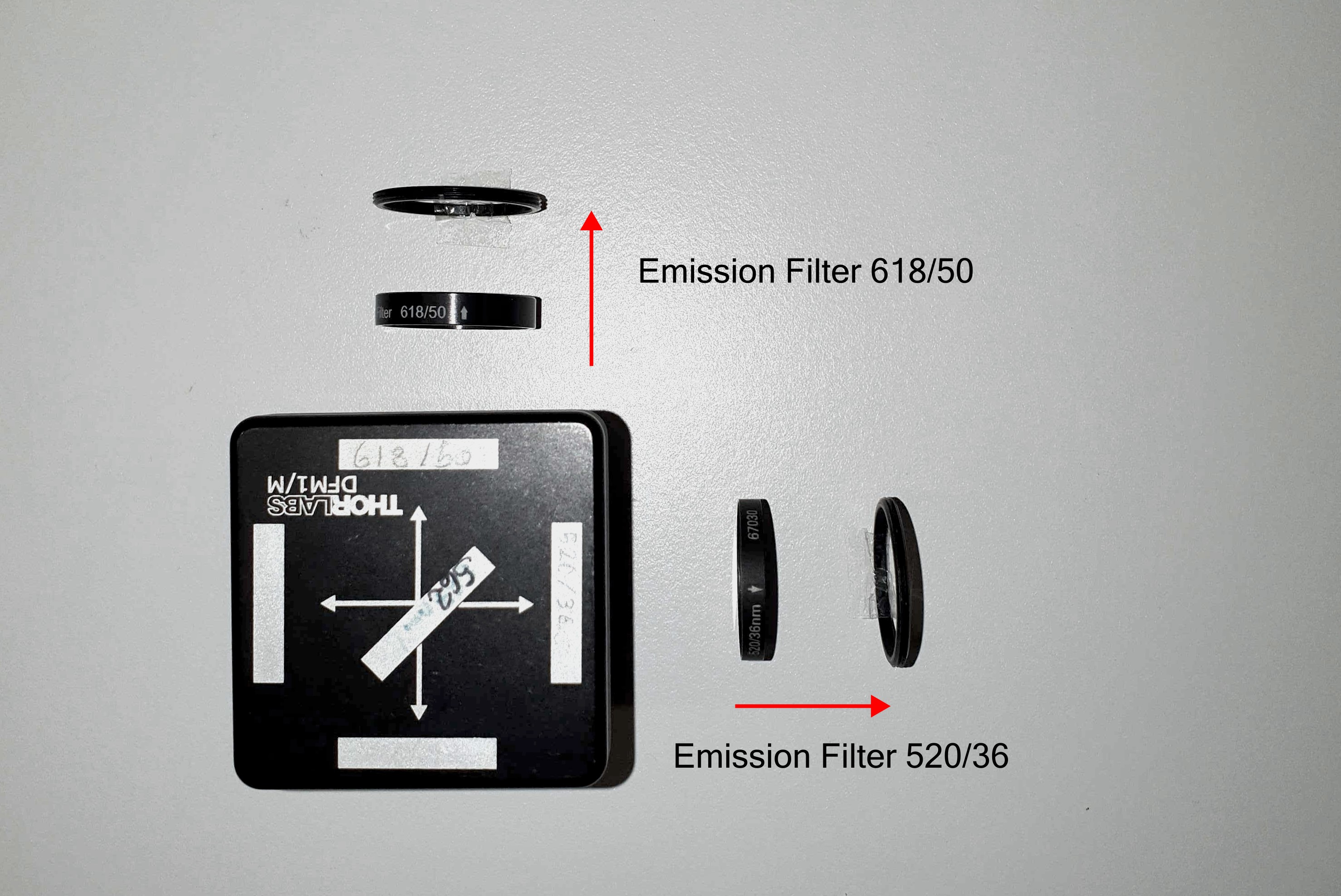
Here you will need one of the two 561nm longpass dichroics, a 618/50 nm bandpass for the red image and a 520/36 bandpass for the green image.
Follow the steps above to secure the dichroic. Add the two filters, the red at the top and the green at the right side of the filter. The 'top' and 'right' orientation refers to the cube's placement when you are looking at it in the microscope. Since the filters are from Semrock and Edmund Optics, the direction of the arrows should follow the direction of the light, i.e. outward of the cube and toward the camera as depicted below.
Filter cube 3 - Image merge cube
This cube combines the red and green images. You will only need the final 561nm longpass dichroic. Secure it in the cube as described above. Orient the front side of the mirror toward the red channel.
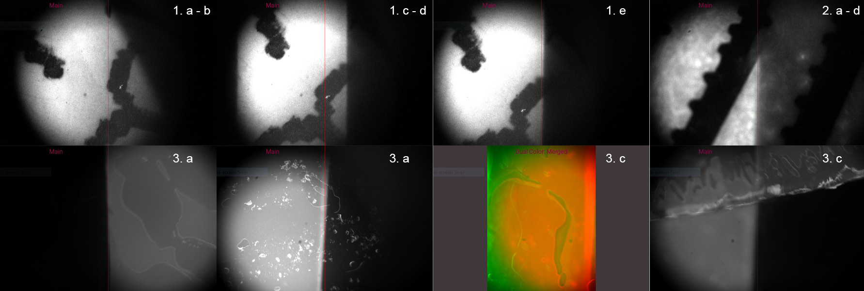
Adjust field-of-view for dual color imaging
To adjust the field-of-view for dual color imaging we first need to align the mirrors such that dual color images are projected onto the camera side by side without overlapping. Before starting, ensure that your GlowTracker settings are ‘dual color’ and the view is set to ‘splitted’. Turn off all environment lights to avoid seeing double images. Follow the instructions below to align both images. You will need dual colored samples. We found that fluorescent tape or even fluorescent markers on a glas slide work well.
- Positioning of first color channel (here red):
- Concentrate on the red channel first, for this block the green channel by removing the image splitter cube (the middle cube)
- Focus on a sample using the z-axis of the stage. A white paper with small printed letters or a barcode works well
- Focus the slit, by rotating the adjustable element, until its edges come sharp in focus (the sample needs to be in focus too)
- Loosen the screws of the adapter that holds the camera in place, rotate the camera so that the slit is orientated vertical to the image of the camera
- Use screws at the mirror mount of the red channel to move the image, so that the highest intensity is in the center of one of the sides. Note that there are 3 ways to adjust the mirror: 2 screws and one hole requiring a hex key that moves the image diagonally.
- Put back the middle cube
- Alignment of second color channel (here green):
- Block the light of the red channel if possible, e.g. by putting a piece of paper in the red light path.
- Use the screws of the mirror mount of the green channel to first find the edge of the slit, and second position the green image as in 1. e
- Unblock the red light
- Adjust the position of the green image so that the structures are approx. at the same position (in the split view) as in the red channel
- Test the alignment by using fluorescent samples (e.g. fluorescent tape)
- Test if the split view shows images only in the expected wavelength i.e., red samples show up on one side and green samples on the other side.
- Check alignment on sample with both wavelength (e.g. use yellow fluorescent tape, or overlay red and green fluorescent tape)
- Adjust alignment if necessary, you can also use the merged view (-> GUI/ Settings)
- Try to keep the highest intensity in the center of the images
- Dual color calibration
- Open the calibration menu at the right of the GlowTracker GUI
- Open the dual color calibration mode and press calibrate
- If the calibration is not good try to find either a better part of the sample or try to focus both sides, repeat the calibration
- Check alignment on biological samples